
A wrong interpretation of a single symbol on a bulb flat drawing can lead to ordering tons of incorrect steel. This mistake costs money and delays critical shipbuilding projects.
Reading bulb flat steel drawings requires understanding standard structural drawing principles, focusing on key symbols for bulb flats, and correctly interpreting dimensions, tolerances, and material callouts. It combines skills from reading general steel structures, reinforcement, construction plans, and size notations.
Bulb flats are not like standard beams. Their unique "T" shape with a rounded bulb means their drawings use specific symbols. Many buyers feel confused when they first see these technical documents. I will guide you through the logical steps, starting from broader principles and moving to the specifics of bulb flats. This process will turn a confusing drawing into a clear purchase order.
How to read steel structure drawing?
You open a ship’s structural drawing. You see a web of lines, numbers, and symbols. It looks overwhelming. This feeling is normal. But every complex drawing is built from a set of simple, repeated rules.
Reading a steel structure drawing starts with identifying the title block, revision notes, and general notes. Then, understand the drawing views (plan, elevation, section). Finally, locate and interpret the key symbols, dimensions, and member callouts that define each steel piece, like bulb flats, beams, and plates.
Decoding the Blueprint: A Step-by-Step Method
Think of a structural drawing as a specialized language. You need to learn its alphabet and grammar. Let’s break down the process into manageable steps. This method applies to any steel structure, whether it’s a ship, a bridge, or a building.
Step 1: Master the Drawing Frame (The Meta-Data)
Before you look at any lines, examine the border of the drawing.
- Title Block1: This is usually in the bottom-right corner. It tells you the project name, drawing title (e.g., "Midship Section"), drawing number, scale, and who created it. The drawing number is crucial for tracking revisions.
- Revision Block2: This lists all changes made to the drawing. Always check the latest revision. Using an outdated drawing is a major error.
- General Notes3: This section contains critical information that applies to the entire drawing. It specifies the standard (e.g., "All dimensions in mm"), the material grade (e.g., "Steel to be AH36 unless noted"), welding specifications, surface preparation requirements, and reference standards (like ISO or ASTM).
Step 2: Understand the Views
A 3D object is shown on 2D paper using different views.
- Plan View4: This is a view looking straight down from above. For a ship, it’s the deck plan or bottom plan.
- Elevation View: This is a view looking from the side (sheer elevation) or from the front/back.
- Section View: This is a "cut-through" view. A line on the plan or elevation, labeled "Section A-A", means you should look at a separate drawing that shows what the structure looks like if you cut it along that line. This is where you often see the detailed profiles of bulb flats and other sections.
Step 3: Locate and Interpret Symbols and Callouts
This is the core skill. The drawing uses lines, symbols, and text to represent physical objects.
- Line Types: Solid lines are visible edges. Dashed or hidden lines show edges that are behind another surface. Center lines (alternating long and short dashes) show symmetry or center points.
- Member Callouts5: Next to a steel member, you will see a label like
HP 200x12orFB 300x90x10/15. For bulb flats, the callout is key. It might follow a standard likeBulb Flat 200x12or use a symbol. - Dimensions6: Dimensions6 are given with extension lines, dimension lines, and numbers. They define lengths, spacings, and positions.
- Detail Markers7: A circle with a number inside (e.g.,
①) on the main drawing points you to a separate, enlarged "detail drawing" for a complex joint or connection.
This table summarizes the key elements and their purposes:
| Drawing Element | What It Looks Like | Its Primary Purpose | Example for Bulb Flats8 |
|---|---|---|---|
| Title Block1 | A box at the corner with text and tables. | Provides drawing identity, scale, and origin. | Confirms this is the correct hull section drawing. |
| General Notes3 | A block of text, often near the title block. | States universal rules for materials, workmanship, standards. | "All bulb flats to be grade DH36, tolerance per ISO 10721." |
| Section Line | A line labeled "A-A" with arrows. | Indicates where a cross-section is taken. | Shows the cut through a frame where bulb flats are used as stiffeners. |
| Member Callout | Text label next to a member. FB 250x10 |
Identifies the profile type and its key dimensions. | Bulb 180x10 or a symbol leading to a schedule. |
| Dimension | Arrow-headed line with a number. | Defines the size and location of members. | Spacing between bulb flat stiffeners (e.g., 600mm). |
| Detail Marker | A circle with a number (①, ②). | Points to a separate, enlarged view of a complex area. | Shows how the bulb flat is welded to the plate at its end. |
For bulb flats specifically, you often find them in section views, acting as stiffeners on plates. The callout or a symbol will point to a "Profile Schedule" or "Member List" on the same drawing or a separate sheet. This schedule is your shopping list.
How to read steel reinforcement drawings?
Reinforcement drawings focus on concrete, but their logic is identical to steel detailing. They teach you how to follow schedules, bending diagrams, and detailed callouts—skills directly transferable to understanding bulb flat lists and fabrication details.
Reading reinforcement drawings involves interpreting bar schedules, bend shapes, and detailed section views to understand the size, grade, quantity, shape, and placement of rebar within concrete structures. The focus is on schedules and placement, similar to steel member lists.
Learning from Rebar: Schedules and Shapes
Reinforcement drawings are masters of data organization. They don’t draw every single bar. They use a numbering system and a schedule. This is exactly how complex steel structures, like ships with hundreds of bulb flats, are documented. Let’s see how this works.
The Core Concept: The Schedule
A rebar schedule is a table. Each row represents a group of identical bars. The columns give all the information needed to make and place them.
- Mark: A unique identifier (e.g., B1, T12).
- Diameter: The bar size (e.g., 16mm, 25mm).
- Shape Code: A reference to a standard bending shape diagram.
- Length: The total length of the bar after bending.
- Quantity: The number of bars with this exact mark.
Applying This to Bulb Flats
A ship’s structural drawing will have a "Profile Schedule" or "Member List." For bulb flats, this schedule is your most important document. It might look like this:
| Mark | Profile | Length (mm) | Qty. | Material | Remarks |
|---|---|---|---|---|---|
| BF1 | Bulb Flat 200×12 | 7,500 | 24 | DH36 | Frame #5-28, Port & Stbd |
| BF2 | Bulb Flat 180×10 | 3,200 | 12 | AH36 | Longitudinal Stiffener, Hold 2 |
- Mark (BF1): This is the unique tag for this group of bulb flats. On the drawing, you will see the symbol or label
BF1next to each identical bulb flat. - Profile (Bulb Flat 200×12): This is the key.
200is the total height of the bulb flat (from the bottom of the flat to the top of the bulb).12is the thickness (in mm). This notation must be standardized. Sometimes it’s written asFB 200x12. - Length: The cut length for fabrication.
- Qty.: How many pieces of this exact specification you need to order.
- Material: The steel grade (AH36, DH36, etc.).
Reading the Shape Details
Rebar drawings have bend diagrams. Bulb flat drawings have connection details. The main drawing shows the bulb flat as a simple line. A detail marker (like DET. 3) points to a separate, larger-scale drawing. This detail shows:
- How the end of the bulb flat is cut (square, sniped, or with a cope hole).
- The weld specification connecting the bulb flat’s flat side to the ship’s plate.
- Any attachments or brackets welded to the bulb flat.
The skill from rebar drawings is this: Never just look at the picture. Always find the schedule and cross-reference the marks. For bulb flats, the schedule tells you what to buy, and the detail drawings tell you how it will be fabricated and attached.
How to properly read construction drawings?
Construction drawings integrate structure, architecture, and systems. Reading them properly means understanding how different drawing types layer together. A bulb flat drawing is one layer of a much larger ship construction plan set.
Properly reading construction drawings requires a systematic approach: start with site/plan drawings for context, study architectural layouts, then examine structural drawings (like steel frames), and finally review mechanical/electrical/plumbing (MEP) drawings for conflicts. Always check scales, notes, and cross-reference between drawings.
The Layered Approach: From the Big Picture to Your Bulb Flat
A single drawing never tells the whole story. In shipbuilding, you might have hundreds of drawings. Reading them "properly" means knowing the hierarchy and knowing where to find specific information. Let’s apply a construction drawing mindset to a shipbuilding project.
Step 1: Understand the Drawing Set Hierarchy
Drawings are organized from general to specific.
- General Arrangement (GA) Drawings: These are the "master plans." They show the overall layout of the entire vessel—all decks, compartments, and major bulkheads. This is where you get context. You see where the structural members are located.
- Structural Drawings: These are derived from the GA. They include:
- Midship Section Drawing: The most important drawing for understanding the primary hull structure. It shows the typical cross-section, including the size and spacing of frames, longitudinals (often bulb flats), and plates.
- Shell Expansion Drawing: Shows the plating layout on the hull.
- Frame Drawings: Show the details of individual transverse frames.
- Fabrication/Detail Drawings: These are the most specific. They provide instructions for making individual parts or sub-assemblies. A drawing for a "Bulkhead Stiffener Panel" might detail exactly how several bulb flats are welded to a plate.
Step 2: Cross-Referencing is Mandatory
A bulb flat’s callout on the midship section might be Bulb 200x12. To get the full story, you must cross-reference.
- The Frame Drawing will show the exact length of that bulb flat on that specific frame.
- The Profile Schedule (often on the midship section or a separate list) will give you the material grade and total quantity.
- A Standard Detail Drawing will show how the ends of all bulb flats are to be treated.
Step 3: Watch for Conflicts and Notes
Different systems compete for space. On a construction drawing, a pipe might clash with a beam. On a ship, a pipe or electrical conduit might need to pass through a cut-out ("cope") in a bulb flat’s web. This is shown on the Piping Arrangement or Electrical Drawings. The structural drawing might note: "Cope as per P&ID Drawing MEP-101." You must check that other drawing.
This layered system is why communication with the fabricator or shipyard is vital. When we receive an inquiry for bulb flats, we ask: "Can you share the specific detail drawing or profile schedule?" This ensures we quote and supply the exact material needed, including the correct length, grade, and any special tolerances for coping or welding mentioned in the notes.
How to read structural steel sizes?
The notation 200x12 for a bulb flat seems simple. But does 200 refer to the web height or the total height? Misreading this will result in steel that does not fit. Structural steel size notation follows strict conventions that you must know.
Reading structural steel sizes involves understanding standardized notation systems for different profiles. For bulb flats, the common notation is Bulb Flat H x t or FB H x t, where H is the total height (flat + bulb) and t is the thickness. Other profiles like I-beams (HP/UB), channels (C/UC), and angles (L) have their own unique notation rules.
Demystifying the Code: A Profile-by-Profile Guide
Each type of steel section has its own "naming language." These notations are condensed codes that give all the key dimensions. Let’s decode them, with a special focus on bulb flats.
Bulb Flat (FB – Flat Bulb) Notation
This is the core of your question. The notation is not universal, but the most common standard (ISO, shipbuilding standards) is:
Bulb Flat 200 x 12orFB 200 x 12- 200: This is the total height (H). It is measured from the bottom of the flat face to the extreme top of the rounded bulb.
- 12: This is the thickness (t) of the steel. This thickness is uniform for both the flat part (the web) and the bulb.
- Other Possible Dimensions: Sometimes you may need the width of the flat part. This is usually a standard proportion relative to the height. For a
200x12bulb flat, the flat width might be around 50mm. If the design is critical, the detailed drawing will specify this.
Comparison with Other Common Marine Profiles
To understand bulb flats better, let’s see how they relate to other sections we supply.
| Profile Type | Common Notation Example | How to Read It | Key Dimensions (Visualize a capital letter shape) |
|---|---|---|---|
| Bulb Flat (FB) | FB 200 x 12 |
Total Height x Thickness. | H=200mm (Total), t=12mm (thick). Looks like a "T" with a round bulb on top. |
| Angle Bar (L) | L 150 x 100 x 12 |
Leg Length x Leg Length x Thickness. | Two legs: 150mm long and 100mm long, both 12mm thick. |
| Flat Bar | FLAT 200 x 20 |
Width x Thickness. | A simple rectangle: 200mm wide, 20mm thick. |
| I-Beam / H-Beam (HP, UB) | HP 310 x 12.7 |
Nominal Depth x Weight per Meter (or Web Thickness). Requires a chart. | ~310mm total height. Exact flange width and web thickness found in standard tables. |
| Channel (C, UC) | C 380 x 100 x 13.5 |
Depth x Flange Width x Web Thickness (approx). | ~380mm tall, flanges ~100mm wide, web ~13.5mm thick. |
Tolerances: The Hidden Part of "Size"
The drawing gives a nominal size (200×12). However, rolled steel sections have permissible deviations. These are defined in standards like ISO 10721 or ASTM A6. The drawing’s general notes will say "Tolerances per ISO 10721." This means:
- The height (200mm) might have a tolerance of ± 3mm.
- The thickness (12mm) might have a tolerance of ± 0.5mm.
- The straightness of the bulb flat over its length is also regulated.
For procurement, this is crucial. You must confirm if the supplier’s mill can meet the specified tolerance standard. When Gulf Metal Solutions asks for stable quality, they are partly asking for dimensional consistency within these tight tolerances, so every bulb flat fits during assembly without extra work.
Putting It All Together: From Symbol to Order
On the drawing, you see a symbol and the label BF3. You find BF3 in the Profile Schedule, which says Bulb Flat 180x10, L=4800mm, Qty=35, DH36. You check the detail drawing for end conditions. You now have a complete specification:
- Product: Bulb Flat (FB)
- Dimensions: 180mm total height, 10mm thickness.
- Length: 4.8 meters, cut to length.
- Quantity: 35 pieces.
- Material: DH36 grade steel (with certified impact toughness).
- Tolerance: As per the noted standard (e.g., ISO 10721).
Only with all this information can you request an accurate quote or place a correct order. Reading the size is the start, not the finish.
Conclusion
Reading bulb flat drawings is a systematic skill. Start with general structural principles, use schedule logic, apply a layered drawing review, and master precise size notation. This turns symbols into a clear, error-free material order.
-
Understanding the Title Block is essential for identifying project details and ensuring accuracy in reading drawings. ↩ ↩
-
The Revision Block helps track changes and ensures you are using the most current version of the drawing. ↩
-
General Notes provide critical guidelines and standards that apply to the entire drawing, ensuring compliance. ↩ ↩
-
A Plan View offers a top-down perspective, crucial for understanding layout and spatial relationships in designs. ↩
-
Member Callouts identify specific steel profiles and dimensions, essential for accurate construction and material ordering. ↩
-
Dimensions define sizes and locations, making them vital for precise fabrication and assembly of structures. ↩ ↩
-
Detail Markers indicate complex areas that require further examination, ensuring clarity in intricate designs. ↩
-
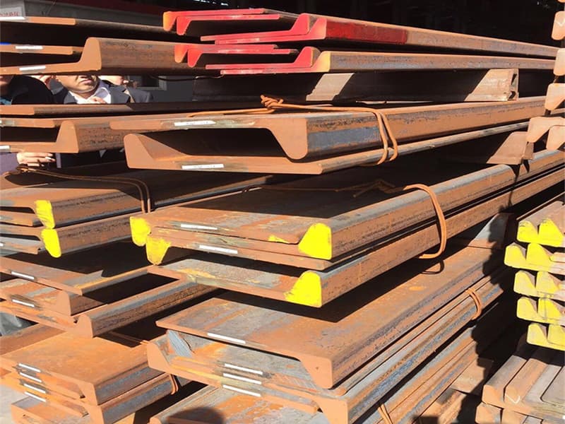
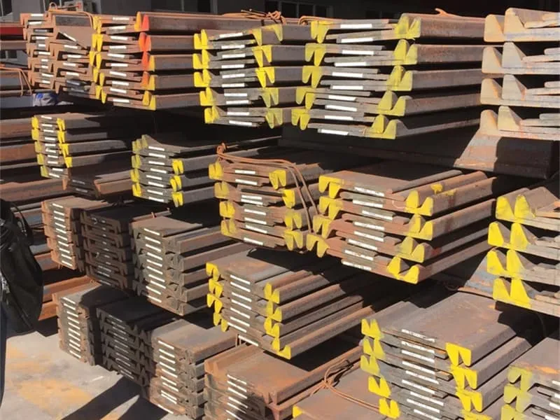
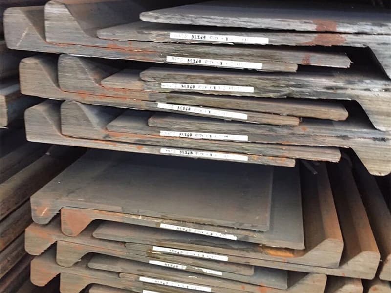
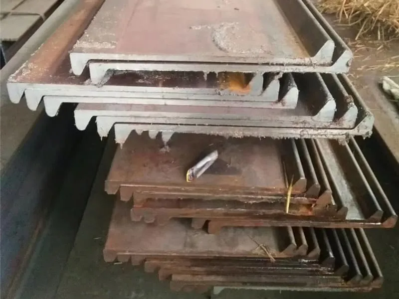
Bulb Flats are key components in structural integrity, and understanding their use is crucial for engineers and builders. ↩