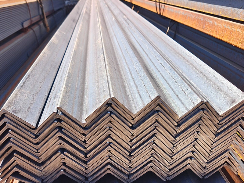
A perfect marine angle steel frame means nothing if it is welded poorly. A bad weld is a crack waiting to happen. It can fail under stress and put the entire vessel at risk. Good fabrication starts with understanding the basics and following proven rules.
Marine angle steel welding and fabrication best practices include proper joint preparation, selecting the correct welding procedure, controlling heat input, and using suitable positions like 1G, 2G, 3G, and 4G. Following the "golden rule" of maintaining correct travel and work angles ensures strong, defect-free welds that meet classification society standards for ship construction.
Many shipyards and fabricators buy our angle steel. I see the results of good and bad welding practices in the feedback we get. The difference is not just in appearance. It is in safety and longevity. In this article, I will share the key technical points every fabricator should know. We will cover welding positions, fundamental rules, and specific techniques. This knowledge will help you build structures that last. Let’s start with the positions that define how a weld is made.
What are the positions for 1G 2G 3G 4G 5G welding?
Welding is not always done in the easy, flat position. On a ship, you weld in every direction. The position codes tell you exactly how the joint is oriented. This is critical for planning and quality control.
The positions 1G, 2G, 3G, 4G, and 5G refer to standardized welding positions for grooves. 1G is flat, 2G is horizontal, 3G is vertical, 4G is overhead, and 5G is pipe fixed (horizontal rolled). For fillet welds on angles, the common positions are 1F (flat), 2F (horizontal), 3F (vertical), and 4F (overhead). Each position requires specific techniques to ensure proper fusion and bead shape.
Understanding and Applying Welding Position Codes
These codes are not random. They are part of a global language defined by standards like AWS and ASME. They tell the welder exactly what challenge they face.
The Logic Behind the "G" and "F"
The letter tells you the joint type. "G" stands for Groove Weld. This is a weld in a groove between two members, like a butt joint between two angle ends. "F" stands for Fillet Weld. This is the most common weld for attaching angles, like welding an angle’s leg to a plate. The number tells you the position.
Breaking Down the Key Positions for Angle Fabrication
For marine angle steel, you will mostly deal with fillet welds (F positions). But understanding groove positions is also important for splicing.
- 1F / 1G – Flat Position: The weld is on the upper side of the joint. The face is nearly horizontal. This is the easiest position. Gravity helps you. You can deposit more metal faster. When possible, rotate the assembly to weld in the 1F position for the best quality and speed.
- 2F / 2G – Horizontal Position: The weld axis is horizontal, but the weld face is vertical. For a 2F fillet weld, one piece is horizontal (like a deck plate) and the other is vertical (like an angle leg). Molten metal wants to sag. The welder must control the arc and travel speed carefully.
- 3F / 3G – Vertical Position: The weld axis is vertical. This is difficult. Molten metal wants to drip downward. For vertical-up welding, you use a slower travel speed and a weaving technique to let the pool solidify. For vertical-down, you use a fast travel speed and a specific angle.
- 4F / 4G – Overhead Position: The weld is performed from the underside of the joint. This is the most challenging position. The welder must counteract gravity directly. It requires the lowest amperage and small weld pools to prevent metal from falling.
Why This Matters in Shipbuilding
A ship is a 3D puzzle. You cannot always weld in the flat position. A welder must be qualified and tested in the specific positions they will use on the job. A procedure qualified for 1F may not be approved for 3F. When fabricators order our angle steel, they already have Welding Procedure Specifications (WPS) that define the approved positions for each joint. The material’s quality must support this. If the steel has inconsistent chemistry or surface contamination, it will be much harder to achieve good welds in difficult positions like 3G or 4G. Good steel behaves predictably under the arc, which is why we emphasize stable quality from certified mills.
| Position Code | Full Name | Joint Orientation (for Fillet) | Key Challenge & Technique |
|---|---|---|---|
| 1F / 1G | Flat Position | Workpiece is flat, weld face horizontal. | Easiest. Focus on proper travel speed and bead size. |
| 2F / 2G | Horizontal Position | One surface horizontal, one vertical. Weld axis horizontal. | Preventing sag on the vertical surface. Use a slight upward angle. |
| 3F / 3G | Vertical Position | Weld axis vertical. | Fighting gravity. Use vertical-up (weave) for penetration, vertical-down for speed on thin material. |
| 4F / 4G | Overhead Position | Welding from underneath the joint. | Metal wants to fall. Use low current, small pool, and fast freeze electrodes. |
What is the golden rule in welding?
Every skilled welder knows one rule above all others. It is not about amperage or rod type. It is about visibility and control. If you break this rule, your weld will likely have defects.
The golden rule in welding is: "If you can’t see it, you can’t weld it." This means you must always maintain a clear, unobstructed view of the weld pool and the leading edge of the joint (the "toe of the weld"). Proper positioning, lighting, and helmet selection are essential to follow this rule and produce consistent, high-quality welds.
The Critical Importance of the Weld Pool
The weld pool is not just molten metal. It is your live feedback system. It tells you everything about what is happening in the joint.
What the Weld Pool Shows You
When you look at the pool, you can see:
- Penetration: The depth the fusion is going into the base metal. A properly penetrated weld has a certain fluidity and shape at the edges.
- Contamination: Oil, rust, or paint will cause the pool to bubble, spit, or become erratic.
- Travel Speed: If you move too fast, the pool becomes elongated and narrow. If you move too slow, it becomes wide and can overheat.
- Arc Length: A long arc makes a wide, shallow, and noisy pool. A correct, short arc makes a tighter, more controlled pool with a crisp sizzle.
If your view is blocked by your hand, the electrode holder, or smoke, you lose this information. You are welding blind. You might think you are on the joint, but you could be off to one side, causing lack of fusion. This is a critical defect, especially in marine structures.
Practical Ways to Follow the Golden Rule
- Body Position and Comfort: Position yourself so you are not stretching or straining. You need a stable stance to hold the torch or electrode steady. This allows you to keep your head in the right place to see.
- Lighting: Shipbuilding often happens in shaded or indoor areas. Use task lighting to illuminate the joint clearly. A dark joint makes it impossible to see the edges before you strike the arc.
- Welding Helmet and Lens: Use a high-quality auto-darkening helmet. Set the delay and sensitivity correctly so the lens stays dark only as long as needed. Use a clear cover lens and change it often when it gets spattered. For intricate work on angle brackets, a cheater magnifying lens can help.
- Remove Obstructions: Clean the joint area thoroughly. Grind off any spatter from previous passes. This gives you a clean path to see.
Consequences of Ignoring the Rule
When you weld blind, defects happen. Lack of fusion is the most common. The weld metal does not bond properly with the base metal. It looks okay on the surface but is just sitting on top. Under load, it can peel off. Porosity (gas bubbles trapped inside) can also occur if you cannot see the pool solidifying properly. For our clients who fabricate ship frames, these internal defects are a major concern. They use non-destructive testing (NDT) like ultrasonic or magnetic particle inspection to find them. A high reject rate costs them time and money. Starting with good steel and welders who follow the golden rule is the best prevention.
| Aspect of the Rule | Why It Matters | How to Achieve It | Common Mistake |
|---|---|---|---|
| See the Weld Pool | Monitor fusion, travel speed, and cleanliness in real-time. | Position your head directly in line with the weld, not at an angle. | Leaning back or to the side, losing the direct view. |
| See the Joint Ahead (Toe of the Weld) | Ensure the arc is precisely on the joint path. | Use adequate lighting and keep the arc area clear of smoke with ventilation. | Welding in a shadow or through smoke cloud. |
| Maintain a Clear Line of Sight | Keep vision unobstructed from helmet to pool. | Choose the right size electrode holder/torch and grip it in a way that keeps your hand out of the way. | A large glove or awkward grip blocking the view. |
Is a 20° to 35° travel angle recommended for downhill welding?
Downhill welding is a specific technique. It is fast but requires precise control. The travel angle is one of the most important settings. The common recommendation exists for a good reason.
Yes, a 20° to 35° travel angle (also called a drag angle) is generally recommended for downhill welding with processes like SMAW (stick) and FCAW (flux-cored). This angle points the electrode or gun back toward the completed weld. It helps control the molten pool, provides a shielding gas cover, and allows for higher travel speeds on thinner materials, like many marine angle steel sections.
Mastering the Downhill Technique
Downhill welding is not just welding in a downward direction. It is a distinct procedure with specific goals and risks.
Understanding Travel Angle
The travel angle is the angle between the electrode (or welding gun) and a line perpendicular to the weld axis, in the plane of the weld. When the electrode points back toward the finished weld, it is a drag or backhand angle (positive). When it points ahead, it is a push or forehand angle (negative). For downhill, you use a drag angle.
Why 20° to 35° Works for Downhill
This range is a balance of several factors:
- Pool Control: Gravity pulls the molten metal downhill. A drag angle points the arc force up against this flow. This arc force helps hold the pool back, preventing it from running too far ahead and creating a thin, weak weld.
- Shielding: In shielded metal arc welding (SMAW), the flux coating creates a gas shield. A drag angle ensures this shield covers the molten pool and the hot, solidifying weld metal behind it, protecting it from atmospheric contamination.
- Penetration Profile: Downhill welding naturally gives shallower penetration than uphill. A drag angle within this range provides enough penetration for many fillet welds on angle steel, while the speed prevents burn-through on thin legs.
Applications and Limitations in Marine Fabrication
Downhill is excellent for:
- Thin Material: Joining thin angle legs (e.g., 5mm to 8mm) to plates.
- High-Speed Production: Where full-penetration is not critical, like for non-structural attachments or sealing welds.
- Root Pass on Open-Gap Joints: It can help quickly lay in a root pass.
However, downhill welding is often NOT recommended for:
- Critical Structural Joints: Where deep penetration and maximum strength are required (e.g., primary hull frames). For these, vertical-up (3G uphill) is standard.
- Thick Sections: The shallow penetration is insufficient.
- Poor Fit-Up: If the gap is large, downhill can lead to lack of fusion.
A Practical Note from the Field
Many shipyards use downhill welding for specific applications on angle stiffeners. They train their welders to maintain a consistent 25-30° drag angle. They also control other parameters tightly: using smaller diameter electrodes (like 2.5mm or 3.2mm), higher amperage at the top of the range, and a fast, steady travel speed. The quality of the steel matters here too. If the angle steel has a smooth, clean surface, the arc starts and runs smoothly, making it easier for the welder to maintain that perfect angle. Inconsistent mill scale or rust can cause the arc to flicker, forcing the welder to adjust constantly and potentially losing the correct angle.
| Welding Parameter | Typical Downhill Setting | Reason | What Happens If Wrong |
|---|---|---|---|
| Travel Angle | 20° to 35° Drag | Controls pool, provides shielding. | Angle too small: poor shield, pool runs away. Angle too large: excessive penetration, spatter. |
| Travel Speed | Fast and steady | Prevents excessive heat buildup and burn-through. | Too slow: melt-through, warping. Too fast: lack of fusion, thin bead. |
| Amperage | Higher end of range for electrode | Ensures proper fusion at high speed. | Too low: stubbing, poor fusion. Too high: uncontrollable pool, undercut. |
| Electrode/Gun Position | Directly on joint, slight weave if needed. | Maintains consistent fusion to both sides of a fillet. | Wandering off joint leads to lack of fusion on one leg. |
What angle should you be at when stick welding?
This seems like a simple question, but it has two answers. There is the work angle and the travel angle. Both are vital for making a sound weld, especially on an L-shaped piece of steel.
When stick welding, you must control two angles. The work angle is typically 45° for a flat fillet weld between two perpendicular pieces (like an angle to a plate). The travel angle is usually a 5° to 15° drag angle for flat/horizontal positions. These angles ensure even heat distribution and proper fusion into both sides of the joint.
The Dual-Angle System for Precision Welding
Thinking of just one "welding angle" is a mistake. Professional welders manage both angles simultaneously to direct heat and metal exactly where it is needed.
1. Work Angle: Dividing the Heat
The work angle is the angle between the electrode and the line perpendicular to the joint axis, measured in a plane perpendicular to the weld axis. For a T-joint or fillet weld (where an angle leg meets a plate at 90 degrees), the ideal work angle is 45 degrees. This points the arc and heat equally at both pieces (the toe of the angle and the face of the plate). This ensures the molten pool fuses equally into both sides. If you hold the electrode at a 30-degree work angle, you direct 70% of the heat to one side and only 30% to the other. This can cause lack of fusion on the cooler side and undercut on the hotter side.
2. Travel Angle: Directing the Pool
As discussed earlier, the travel angle is in the plane of the weld. For most stick welding in the flat (1F/1G) or horizontal (2F) positions, a slight drag (backhand) angle of 5° to 15° is standard. This angle helps the flux shield cover the solidifying crater. It also gives the welder a better view of the pool. A push (forehand) angle is sometimes used for specific applications but can lead to less penetration and a higher risk of porosity.
Applying This to Marine Angle Steel
Imagine welding a 100x100x10mm angle bar as a stiffener to a hull plate. You will make a fillet weld along the length of the angle.
- For a Horizontal Fillet Weld (2F position): The plate is horizontal, the angle leg is vertical. Your work angle is still 45 degrees between the electrode and the two surfaces. But because gravity acts sideways, you might adjust it slightly (e.g., 40-50 degrees) to favor the vertical piece slightly and prevent undercut. Your travel angle is a 5-15 degree drag along the joint.
- For an Overhead Fillet Weld (4F position): This is very difficult. The work angle remains around 45 degrees. The travel angle is critical—often a very slight drag or even perpendicular—to prevent the molten metal from falling. The electrode is held very close to the joint.
The Role of Electrode Type
The recommended angles can change with the electrode. A 7018 low-hydrogen rod, common in shipbuilding for its toughness, runs best with a very short arc and a steady drag angle. A 6010 cellulose rod, used for fast, deep penetration on dirty metal, can tolerate a more aggressive drag angle. The Welding Procedure Specification (WPS) for the job will often specify the acceptable angle ranges.
Quality Starts with the Material
A welder can have perfect technique, but poor material makes it impossible. If the angle steel’s dimensions are inconsistent, the joint fit-up is poor. The welder then has to compensate by manipulating angles, which can lead to defects. If the steel surface is contaminated, the arc becomes unstable, making it hard to maintain any angle. We ensure our marine angle steel has clean, consistent surfaces and precise dimensions. This gives the fabricator’s welders the best possible starting point to apply their skills and maintain the correct angles for a perfect weld.
| Angle Type | Definition | Ideal for Flat Fillet (1F) | Purpose |
|---|---|---|---|
| Work Angle | Angle between electrode and joint perpendicular, relative to the two workpieces. | 45° | Distributes heat equally between the two sides of the joint for balanced fusion. |
| Travel Angle (Drag) | Angle between electrode and line perpendicular to weld axis, pointing back at finished weld. | 5° to 15° | Provides shielding gas/flux coverage, improves visibility, and helps control the weld pool. |
| Combined Effect | Using both angles correctly. | 45° work + 10° drag | Directs heat and filler metal precisely into the root of the joint for a strong, symmetrical weld bead. |
Conclusion
Strong marine structures depend on correct welding practices. Master the standard positions, follow the golden rule of visibility, and control your work and travel angles precisely. These fundamentals, applied to quality steel, ensure durable and safe ship frames.