
Leading paragraph:
You order a batch of marine angle bars. But when the parts come off the machine, some are twisted. Others do not fit. You lose material and time.
Snippet paragraph:
Optimizing cutting and nesting of marine angle bars starts with choosing the right material grade, using software designed for profiles, improving your tooling, and connecting your design data directly to the cutting machine. This cuts waste and keeps parts accurate.
Transition Paragraph:
I have been in the marine steel business for years. I talk to fabricators every day who struggle with the same problems. Let me show you what actually works. We will go through four key areas that will change how you handle angle bar cutting.
Why Does Material Grade and Thermal Control Matter So Much?
Leading paragraph:
You pick a standard grade to save money. Then the heat from cutting warps the steel. The parts do not line up during welding. Now you pay double.
Snippet paragraph:
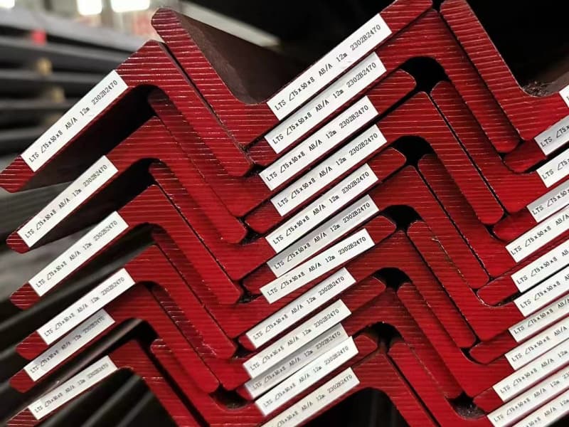
The grade of marine angle bar1 determines how it reacts to cutting heat. Higher grades with controlled carbon content resist distortion better. Proper thermal control2 during cutting keeps the profile straight.
Dive deeper Paragraph:
I learned this lesson from a client in Saudi Arabia. They bought angle bars from a low-cost supplier. The material looked fine on paper. But when their fabricators started cutting, every piece twisted. They spent hours straightening parts. That is why I always tell my customers: the material grade3 is not just a number. It decides if your cutting process will be smooth or a nightmare.
Let us break this down into three simple points.
1. The Chemistry of the Steel
Marine angle bars face constant exposure to salt and moisture. So they need good corrosion resistance4. But the same elements that fight rust can also affect how the steel handles heat.
| Element | What It Does | Effect on Cutting |
|---|---|---|
| Carbon | Increases strength | Too much carbon makes heat-affected zones harder and brittle |
| Manganese | Improves toughness | High levels need slower cutting speeds |
| Silicon | Boosts corrosion resistance | Can create harder scale on cut edges |
If the chemistry is not balanced, you get hard spots. Those spots slow down the torch. They also create uneven heat. That heat leads to warping.
2. The Cutting Method You Choose
Most shops use plasma or laser for angle bars. Plasma is fast. But it puts a lot of heat into a small area. Laser is more precise. But it can be slower on thicker sections.
For marine angle bars, I often recommend high-definition plasma with water cooling. The water table pulls heat away fast. It stops the bar from bending. If you use a laser, you need to adjust the feed rate. Going too fast leaves rough edges. Going too slow makes the heat zone too wide.
3. Pre-Cutting Preparation
I always tell buyers: do not cut right after the steel arrives. Let it sit in your shop for a day. Let it get to room temperature. Cold steel reacts differently to heat. It can crack along the cut edge if it is too cold.
Also check the straightness before you cut. If the bar is already bent, cutting will make it worse. You need to straighten it first. That is a simple step that many shops skip.
In my experience, the shops that control these three factors get the cleanest cuts. Their parts fit on the first try. They do not waste steel fixing mistakes. So when you buy marine angle bars, ask about the carbon content and the heat treatment. That small question can save you weeks of rework.
How Can Nesting Software Handle Angle Bar Specifics?
Leading paragraph:
You use nesting software for flat plates. But angle bars are different. They have a shape. They have a direction. The software does not understand that.
Snippet paragraph:
Nesting software for angle bars1 must account for the profile’s orientation, the flange direction, and the cutting sequence. Specialized modules for shipbuilding profiles handle these variables automatically.
Dive deeper Paragraph:
I visited a shipyard in Vietnam a few years ago. They had just bought a new nesting system. It worked fine for plates. But for angle bars, the operator had to manually rotate each part. It took hours. They asked me if this was normal. I told them no. The right software should treat angle bars differently.
Why Angle Bars Are Not Just “Plates on Edge”
An angle bar has two legs. They are not the same size. One leg is usually longer. That shape changes how you nest it.
- Orientation matters: If you flip the bar, the leg position changes. The part might not fit on the next assembly.
- Mirroring is key: Many angle bar parts are left and right versions. Good software will nest them as pairs. This cuts waste in half.
- End cuts need compensation: The software must add extra length for the cut. Otherwise the finished part comes up short.
Features to Look For in Nesting Software
| Feature | Why It Matters |
|---|---|
| Profile-specific libraries2 | The software knows the leg lengths and thickness of each angle bar size |
| Pair nesting | Automatically nests mirrored parts side by side |
| Cutting sequence optimization3 | Controls the order of cuts to stop the bar from shifting |
| Kerf compensation4 | Adjusts for the width of the cut to keep final dimensions accurate |
| Remainder management | Keeps track of leftover lengths for future jobs |
The Cost of Using Generic Software
Generic nesting tools treat angle bars as rectangles. They do not know about the flange. So they put cuts too close to the edge. That can weaken the part. They also do not group parts by the same bar size. So you end up switching bars too often. Each changeover costs time.
I tell my clients to look for shipbuilding-specific modules. They cost more upfront. But they pay back in three months. One client in Malaysia cut his scrap rate from 18% to 9% just by switching software. That is real money when you buy steel by the ton.
What Tooling and Fixture Innovations Work for Complex Cuts?
Leading paragraph:
You invest in a high-end cutting machine. But the parts still move during cutting. The torch hits the work. You lose a batch. Frustration builds.
Snippet paragraph:
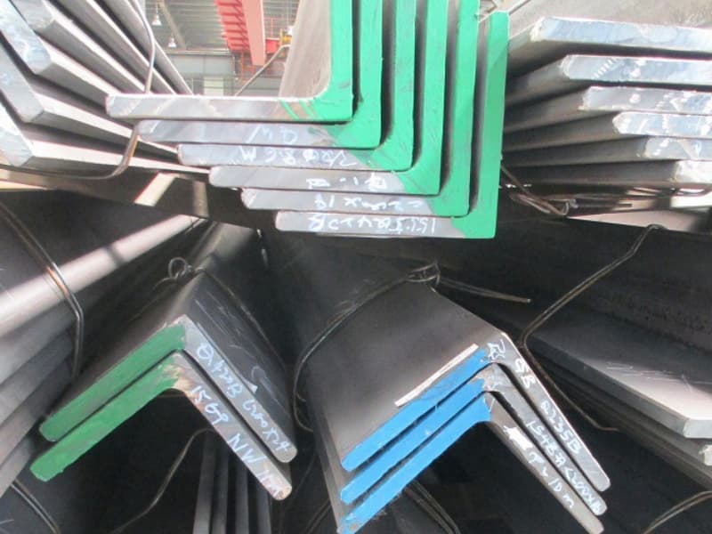
The right fixtures and tooling hold the angle bar in place during cutting. They also allow for expansion and contraction. Simple innovations like clamp positioning and roller supports make complex cuts possible.
[^1] holding an angle bar during CNC cutting](https://cnmarinesteel.com/wp-content/uploads/2025/10/Marine-angle-steel-7.jpg)
Dive deeper Paragraph:
A buyer from Qatar once called me with a problem. He had a new CNC machine. But every time he cut a long angle bar, the end would drop. The torch would crash. He thought the machine was broken. It was not. He just did not have the right support system.
The Physics of Cutting Angle Bars
When you cut an angle bar, the heat makes it expand. Then it cools and contracts. If the bar is clamped too tight, it cannot move. So it buckles. If it is not clamped enough, it shifts. You need a system that holds the bar but lets it breathe.
Here are three simple innovations I have seen work well.
1. Roller Supports with Adjustable Height2
Long bars need support along their whole length. Fixed tables are okay for short pieces. But for 12-meter bars, you need rollers that move with the bar. They should be at the same height as the cutting bed. If they are too high, the bar bends up. Too low, it sags.
2. Pneumatic Clamps with Programmable Pressure3
Old-style manual clamps put the same force everywhere. But an angle bar has different thicknesses. The leg is thick. The corner is thin. If you clamp the thin part too hard, you crush it. Modern pneumatic clamps let you set different pressures for different zones. You can also program them to release during certain cuts so the bar can expand.
3. Drop-Bed Systems for Offcuts4
When you cut a part from the end of a bar, that piece becomes free. It can fall or tilt. If it falls, it might damage the machine. If it tilts, it can hit the torch. A drop-bed system has support fingers that retract after the cut. The part drops straight down into a bin. No tilting. No crashes.
A Real-World Example
One of my customers in the Philippines builds small fishing boats. He uses angle bars for frames. He does not have a big budget for tooling. So we designed a simple rail system with wooden blocks and adjustable clamps. It cost him almost nothing. But his cutting speed went up by 30%. His parts were more consistent. Sometimes the simple solution is the best one.
The key is to match your fixture to the parts you cut most. If you cut short brackets, use strong point clamps. If you cut long stringers, use full-length support. Do not try to make one system do everything. That is how problems start.
How Does Data-Driven Workflow Integration Help from Design to Cutting?
Leading paragraph:
Your designer creates a model. Then someone re-draws it for cutting. Then another person enters the data into the machine. Three steps. Three chances for error.
Snippet paragraph:
Data-driven workflow1 connects the design software directly to the cutting machine2. The model becomes the cutting file. No manual re-entry. This eliminates errors, speeds up setup, and keeps the design intent intact.
Dive deeper Paragraph:
I remember a client in Romania who had a great design team. They made perfect 3D models. But the cutting shop was in a different building. They printed the drawings and walked them over. The cutting operator would re-type the dimensions. Mistakes happened. Parts did not fit. They blamed the steel supplier. But the steel was fine. The problem was in the workflow.
Breaking Down the Data Chain
Let me walk you through how data should flow. Then I will show you where it usually breaks.
Step 1: Design in CAD
The naval architect designs the ship structure. They use software like ShipConstructor or AutoCAD. The angle bar is shown in its exact position. The ends are cut to match the hull shape.
Step 2: Export to Nesting Software
The nesting software3 should import that file directly. It should see the part, its material, its thickness, and its cut angle. No redrawing.
Step 3: Nesting and Sequencing
The software arranges the parts on the bar stock. It picks the best bar size. It decides the cutting order. It adds kerf compensation. All of this is automatic.
Step 4: Generate Machine Code
The nesting software outputs code that the cutting machine understands. This is called G-code or CNC code4. The operator does not type anything. They just load the bar and press start.
Where the Problems Start
| Problem Point | What Goes Wrong | Cost |
|---|---|---|
| Manual redrawing | The part dimensions change slightly | Parts do not fit in assembly |
| Separate nesting by hand | The operator guesses the best layout | Scrap rates go up 10–15% |
| Typed machine code | One wrong number crashes the torch | Machine downtime and material loss |
| No feedback loop5 | Mistakes repeat on future jobs | No improvement over time |
How We Fixed It for a Client in Mexico
A Mexican contractor building offshore structures came to me. He was buying angle bars from me. But he kept asking for extra material because of scrap. I asked to see his workflow. He was printing DXF files and having his operator manually nest them in a basic software. It took two hours per job.
We set up a direct link from his design software to his nesting system. Now his designer nests the parts while he designs. The machine code is ready when the steel arrives. His scrap went from 14% to 6% in three months. He told me the steel cost was not the issue. The labor and waste were killing him.
The Principle to Remember
Data should only be entered once. After that, it should flow. Every time you touch the data by hand, you add risk. You also add time. In a competitive market, time is the real currency. The shops that get their parts cut faster and more accurately win the contracts. That is why I push my clients to connect their systems. It feels like a big step. But once you do it, you never go back.
Conclusion
Optimizing marine angle bar cutting and nesting comes down to four things: better material choices, smarter software, solid fixtures, and connected workflows.
-
Explore how data-driven workflows can streamline processes and reduce errors in manufacturing. ↩ ↩ ↩
-
Learn about the technology behind cutting machines and their role in efficient production. ↩ ↩ ↩ ↩
-
Discover the benefits of nesting software in optimizing material usage and reducing waste. ↩ ↩ ↩ ↩
-
Understand the importance of G-code in automating CNC machines for precision cutting. ↩ ↩ ↩ ↩
-
Learn how feedback loops can enhance continuous improvement and quality control in manufacturing. ↩