
Mixing different steel profiles on a ship frame can create weak spots. Many fabricators get the combination wrong.
You combine marine angle steel, bulb flat, and L sections by matching their stiffness, using the right weld sequence, and designing smooth load paths. This gives you a lighter but stronger hull.
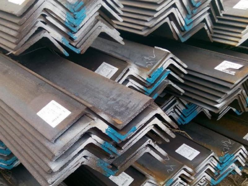
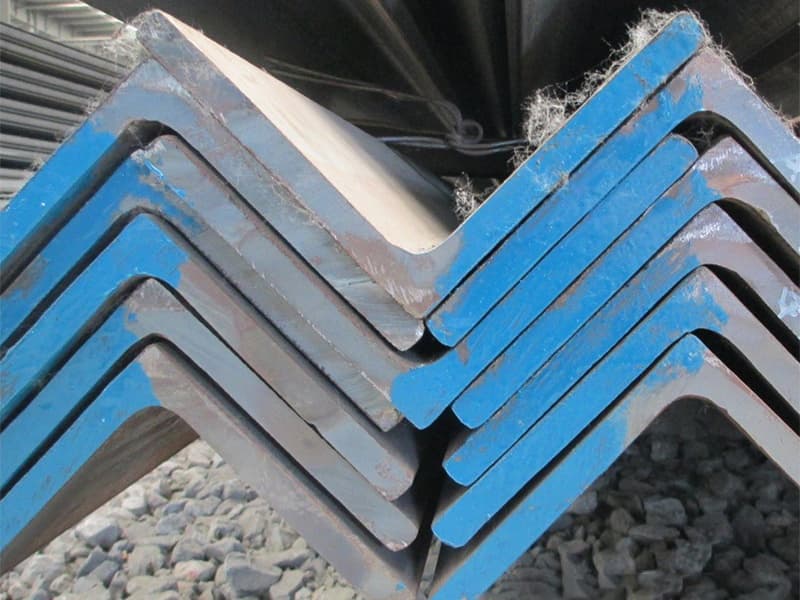
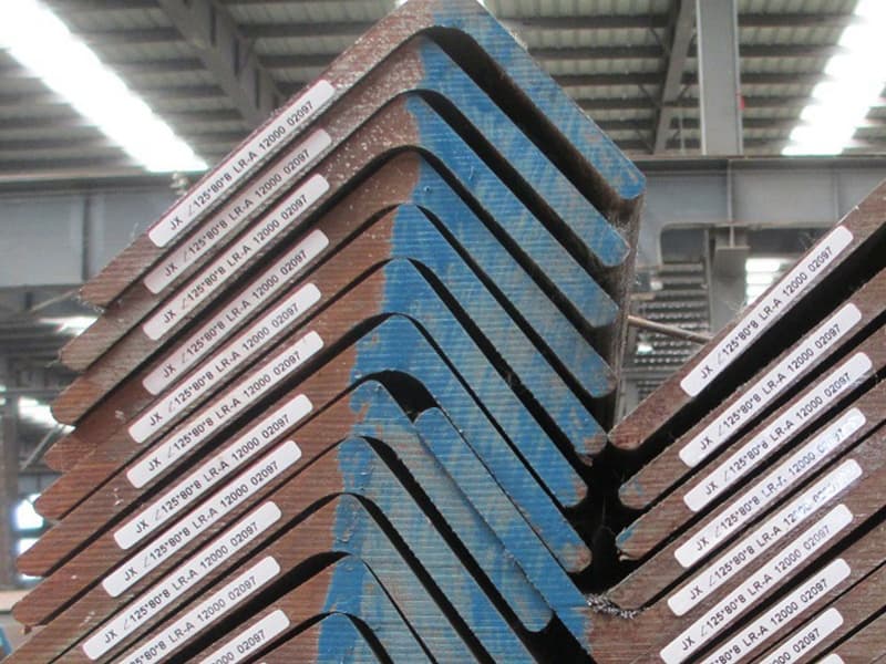
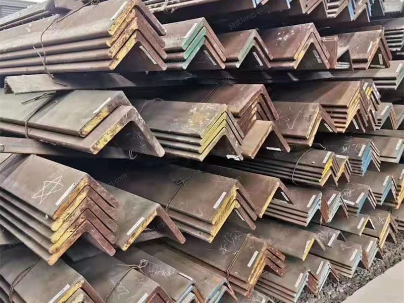
I have helped shipbuilders from Vietnam to Saudi Arabia put these profiles together the right way. Each profile has a job. Angle steel gives you a stiff edge. Bulb flat saves weight. L sections work well in tight corners. But if you just weld them without a plan, you get cracks and stress points. Let me walk you through four practical questions my customers ask me most.
What Is the Best Welding Sequence for Joining Marine Angle Steel and Bulb Flat?
Weld in the wrong order, and your frame pulls out of shape. I have seen angle bars twist so badly that the whole panel had to be scrapped.
Start by tack welding all joints. Then weld the bulb flat to the plating first. Then weld the angle steel to the bulb flat. Finally weld the angle steel to the plating. This sequence controls distortion and keeps alignment.
Why does sequence matter so much?
Heat makes steel expand. When you weld, you put heat into a small area. The hot steel wants to grow. The cold steel around it stops that growth. So the hot zone gets squeezed. Then as it cools, it shrinks and pulls on the surrounding metal. That pulling causes distortion.
If you weld everything in one pass, the pulling adds up. The whole assembly can bow or twist. I once got a call from a buyer in Malaysia. His team welded all the bulb flats first, then tried to attach the angle bars. The angle bars did not fit anymore. The gaps were up to 8mm. They had to cut everything apart and start over.
My step-by-step welding sequence1
| Step | What to weld | Key detail |
|---|---|---|
| 1 | Tack welds on all joints | Use small tacks every 300mm to hold position |
| 2 | Bulb flat to plating | Weld from the middle outward to both ends |
| 3 | Angle steel to bulb flat (one leg) | Use a backstep technique2 to spread heat |
| 4 | Angle steel to plating (other leg) | Weld this leg last so it can move freely |
| 5 | All remaining welds | Check alignment before each pass |
The backstep technique explained
Instead of welding in one long line, you break the weld into small segments. You start at the middle and weld backwards. Then you move forward and weld another segment backwards. This keeps the heat from building up in one spot.
For a 1-meter long joint, I tell welders to use 100mm segments. Weld segment 5, then segment 4, then segment 3, and so on. It takes a bit longer. But the final shape stays flat. A buyer from Thailand tried this after fighting distortion for months. He told me his rework time dropped by 70%.
What about preheating3?
For thicker sections, say over 15mm, you should preheat both the angle steel and bulb flat to about 100°C. Use a propane torch or induction heater. Keep the heat even. Do not just blast one spot. Preheating slows down the cooling rate. That reduces the risk of hydrogen cracking. I always recommend a low-hydrogen electrode4 like E7018 for these mixed joints.
So remember: tack first, then bulb to plate, then angle to bulb, then angle to plate. Use backstep welding. Your frame will stay straight.
How Do You Design a Smooth Load Transition Between an L Section and a Marine Angle Bar?
Loads do not like sharp corners. If you just butt an L section against an angle bar, the stress jumps up at the meeting point. That is where cracks start.
You design a smooth load transition by adding a tapered doubler plate1 or by grinding a gradual radius on the ends of both profiles. The goal is to spread the load over a longer distance, so no single point takes all the force.
What happens at a bad transition?
Imagine you have a heavy load pushing down on a frame. The force travels through the L section. Then it hits the end of the L section. There is no steel beyond that point. So the force has to jump across to the angle bar. But the angle bar is only connected by a weld at that exact line. That weld now carries all the load. The stress level at that line can be three or four times higher than in the middle of the bar. That high stress will eventually cause a fatigue crack2.
I saw this on a bulk carrier in the Philippines. The designer had simply cut the L sections square and butted them against angle bars. After two years, every single joint had a crack. The repair cost more than the original fabrication.
Three ways to fix the transition
| Method | How to do it | Best for | Cost level |
|---|---|---|---|
| Tapered doubler plate | Weld a diamond-shaped plate over the joint | High-load areas like the bottom of the hull | Medium |
| Grinded radius | Grind the ends of both profiles to a smooth curve | Light to medium loads | Low |
| Overlap with staggered weld | Overlap the L section and angle bar by 100mm, weld both legs | When you cannot add a doubler plate | Medium |
My preferred method: the diamond doubler3
Cut a plate from the same grade steel as your profiles. Make it 8mm to 12mm thick. Cut it into a diamond shape. The diamond should be about 300mm long and 100mm wide. Center the diamond over the joint between the L section and the angle bar. Weld all four edges of the diamond to both profiles. Use a continuous fillet weld.
The diamond does two things. First, it connects the two profiles together across the gap. Second, it spreads the load gradually. The wide middle of the diamond carries the most load. The pointed ends carry very little. That gradual change stops the stress spike.
I supplied this solution to a customer in Qatar who was building an oil tanker. He was mixing L sections and angle bars in the pump room. The classification society asked for a smooth transition. We used the diamond doubler. The inspector passed it on the first try.
A simple rule for radius grinding4
If you do not want to add doubler plates, you can grind the ends. Grind the last 50mm of the L section into a gradual slope. Do the same on the angle bar. The slope should drop from full thickness down to a sharp edge. Then weld the two sharp edges together. The load now sees a gentle ramp instead of a cliff. This works well for internal bulkheads where loads are moderate.
But remember: grinding takes skill. The slope must be smooth. No notches or gouges. I tell my clients to have a qualified grinder do this, not a general laborer.
When Should You Replace Angle Steel with Bulb Flat to Save Weight Without Losing Strength?
Angle steel is strong but heavy. Bulb flat is lighter. But you cannot just swap one for the other. You need to know when the swap makes sense.
Replace angle steel1 with bulb flat2 when the load is mainly in one direction and the web depth is more than 150mm. Bulb flat gives you the same strength for 15% to 25% less weight, but it is weaker against twisting loads.
Understanding the strength difference
Angle steel has two legs. That gives it high torsional stiffness3. It resists twisting very well. Bulb flat has only one web plus a small bulb. It is very good at resisting bending in one plane. But it twists easily.
So where do you use each?
| Application | Better choice | Why |
|---|---|---|
| Bottom longitudinal frames (bending only) | Bulb flat | Load is straight up and down, no twist |
| Side stringers (bending + some twist) | Angle steel | Ship rolls, so twist happens |
| Deck beams (mostly bending) | Bulb flat | Load is vertical from cargo |
| Corner joints (high twist) | Angle steel | Two legs give you a stiff corner |
| Internal bulkhead stiffeners | Bulb flat | Load is simple and low |
The weight saving formula4
Here is a simple way to compare. Take an angle steel of size L150x90x10. Its weight per meter is about 18.4 kg. Now look for a bulb flat with a similar section modulus. A bulb flat 160×8 has a section modulus close to the angle steel. Its weight is about 14.2 kg per meter. That is a saving of 4.2 kg per meter. On a ship with 500 meters of stiffeners, you save 2,100 kg. That is over two metric tons.
But check the moment of inertia5. For bending in the strong axis, the bulb flat matches the angle steel. For bending in the weak axis, the bulb flat is much weaker. So you only make the swap if the load never comes from the side.
A real example from Gulf Metal Solutions
When I worked with Gulf Metal Solutions in Saudi Arabia, they were building a series of barges. The original design used L200x100x12 angle steel for the bottom longitudinals. Each barge had 400 meters of these bars. The weight was high, and the barges sat deeper in the water than they wanted.
I suggested switching to bulb flat 220×10. The section modulus was actually 8% higher. The weight dropped by 22%. The customer was nervous at first. So we did a small test panel. We loaded it to the expected forces. The bulb flat performed perfectly. They ordered the bulb flat for all 10 barges. The total weight saving was 35 tons. That let them carry more cargo.
When to say no to bulb flat
Do not use bulb flat in areas with impact loads6. For example, near the bow where waves slam into the hull. The single web of a bulb flat can buckle under a side impact. Angle steel has two legs, so it handles impacts better.
Also avoid bulb flat in way of heavy point loads, like under a crane foundation. The concentrated load can twist the bulb flat. Angle steel spreads that load into both legs.
So ask yourself: does the load come from only one direction? If yes, bulb flat saves weight. If you have twist or side loads, stick with angle steel.
What Connection Detail Prevents Stress Concentration When Mixing L Sections and Angle Bars in a Hull?
Stress concentration is the hidden killer of ship frames. You cannot see it, but it grows with every wave. A bad connection detail can turn a small load into a big crack.
To prevent stress concentration, use a soft toe connection1. Grind a smooth radius at the weld start and stop points. Add a small hole at the end of any cutout. And never stop a weld in a corner. These details spread the stress over a larger area.
What is a stress concentration factor2?
Engineers use a number called the stress concentration factor (SCF). A perfect smooth shape has an SCF of 1. That means the actual stress equals the calculated stress. A sharp inside corner might have an SCF of 3 to 5. So the stress is three to five times higher than your calculation. That is why cracks start at sharp corners.
Most ship design rules assume an SCF of 1.5 to 2.0 for typical welded connections. But if you ignore the details, your actual SCF can be 4 or more. Your safe design becomes unsafe.
Four details that lower the SCF
| Detail | What to do | Reduces SCF from … to … |
|---|---|---|
| Weld toe grinding | Grind the weld toe smooth with a burr | 3.5 to 1.8 |
| Radius at corners | Use a 10mm or larger radius instead of a sharp corner | 4.0 to 1.6 |
| Run-off tab | Weld onto a separate tab, then cut it off | 3.0 to 1.4 |
| Hole at slot end | Drill a 6mm hole at each end of a cutout | 5.0 to 2.0 |
The soft toe connection explained
A soft toe means the weld does not end abruptly. You gradually reduce the weld size over a distance of about 25mm. Imagine a ramp instead of a cliff. At the start of the weld, the leg length is full size, say 8mm. Over the next 25mm, you reduce the leg length to zero. This gives the stress a place to spread out.
I learned this from a Romanian ship engineer. He showed me two identical test pieces. One had a soft toe. One had a sharp toe. The sharp toe cracked after 500,000 load cycles. The soft toe lasted over 2 million cycles and still had no crack.
How to apply this to L sections and angle bars
When you weld an L section to an angle bar, you have three critical points:
-
The start of the weld – Do not start the weld right at the edge of the L section. Start 10mm in from the edge. Use a backstep to create a gradual start.
-
The end of the weld – Do not stop at the corner. Wrap the weld around the corner by at least 15mm. Then grind the end smooth.
-
The inside corner where the two profiles meet – This is the worst spot. The L section has an inside radius. The angle bar has its own radius. Where they meet, you have a natural stress concentration. The fix is to add a small fillet weld in the corner. Make it concave, not convex. A convex weld makes the stress worse.
A simple test you can do
Take a piece of soft clay. Press it with your finger. You see the clay flows away from the pressure point. That is stress flowing. Now take a sharp knife and press it into the clay. The clay splits. That is stress concentration. Your weld details should look like the finger, not the knife.
I share this test with every new buyer who asks about connections. It helps them see the problem without any math. Then they understand why I push for soft toes and radius corners.
So remember: grind the weld toes, wrap the corners, add radius to cutouts, and never let a weld stop in a sharp corner. These small details cost almost nothing. But they can double the life of your ship frame.
Conclusion
Combine marine angle steel, bulb flat, and L sections with the right weld sequence, smooth load paths, smart weight swaps, and soft toe connections. Your hull will stay stronger and last longer.
-
Understanding soft toe connections can significantly enhance the durability of welded structures, preventing costly repairs. ↩ ↩ ↩ ↩
-
Learn about SCF to grasp how design choices impact structural integrity and safety in engineering. ↩ ↩ ↩ ↩
-
Understand torsional stiffness to enhance your designs and ensure structural integrity in your projects. ↩ ↩ ↩
-
Discover effective methods to calculate weight savings, ensuring optimal material choices for efficiency. ↩ ↩ ↩
-
Gain insights into moment of inertia and its critical role in ensuring safety and performance in structures. ↩
-
Learn about impact loads to better assess material choices and enhance the durability of your structures. ↩