
You design a ship. You add L‑sections (angle bars) for stiffening. But you are not sure about the size or the connections. Small mistakes cause big problems later.
When designing with marine L sections, you need to pick the right size, thickness, and grade for each hull zone. You also need correct connection details (snipes, brackets), account for corrosion and fatigue, and ensure weldability. These steps keep your structure safe and easy to build.
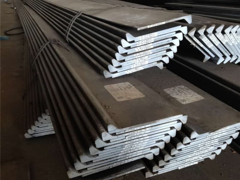
I am Zora Guo. I supply marine L sections to shipyards and designers. I have seen many drawing errors that lead to procurement delays or structural issues. Let me walk you through the key engineering considerations. These come from real feedback from naval architects and fabricators.
How to Select the Optimal L Section Size, Thickness, and Grade for Different Hull Zones?
You open a classification rule book. You see hundreds of L section sizes. Which one fits your deck beam? Which for your side frame? The choice is not random.
Select L section size based on the required section modulus from class rules. Thickness is driven by the plate it stiffens and corrosion allowance. Grade (A, AH32, DH36, etc.) depends on the hull zone stress level and design temperature. Low‑stress areas use Grade A. High‑stress or cold areas use higher grades.
Let me break down the decision process.
Step 1: Determine the Required Section Modulus
The section modulus (cm³) is a measure of bending strength. Classification rules give formulas. For a stiffener, it depends on:
- Spacing between stiffeners (mm)
- Plate thickness (mm)
- Design load (water pressure, cargo load)
Example from ABS rules (simplified):
For a deck stiffener: Required Z = 7.8 x spacing (m) x pressure (kN/m²) x span² (m)
You calculate Z, then look up an L section that meets or exceeds it.
Step 2: Choose Size (Leg lengths and thickness)
L sections come in equal leg (L100x100x10) or unequal leg (L150x90x12). For most ship framing, unequal leg is more efficient. The longer leg is welded to the plate. The shorter leg sticks out.
| Hull zone | Typical L section size (unequal leg) | Typical thickness | Reason |
|---|---|---|---|
| Light deck stiffeners | L75x50x6 to L100x75x8 | 6‑8mm | Low loads, non‑critical |
| Main deck beams | L150x90x10 to L200x100x14 | 10‑14mm | Higher loads, heavier cargo |
| Side frames (small vessels) | L120x80x10 to L160x100x12 | 10‑12mm | Moderate water pressure |
| Bottom stiffeners | L200x100x14 to L250x100x16 | 14‑16mm | High pressure, corrosion allowance |
Step 3: Pick the Steel Grade
| Grade | Yield (MPa) | Charpy temp | Typical zones |
|---|---|---|---|
| A | 235 | +20°C | Superstructure, non‑critical, warm waters |
| B | 235 | 0°C | Upper decks, mild climates |
| D | 235 | -10°C | Side shell, lower decks in temperate zones |
| AH32 | 315 | 0°C | High‑stress zones in warm climates |
| AH36 | 355 | 0°C | High‑stress, warm to moderate |
| DH36 | 355 | -20°C | High‑stress, North Atlantic winter |
| EH36 | 355 | -40°C | Arctic, very cold service |
Rule of thumb: For the same span and load, higher grade allows a smaller L section. But also check the notch toughness requirement.
Step 4: Check Practical Fabrication Limits
Very large L sections (e.g., L300x100x20) are heavy and hard to handle. Sometimes it is better to use a built‑up section (two Ls back to back) or a different profile. Also, very small L sections (L40x40x5) might be hard to source. Always check availability.
I once had a designer specify L65x50x6 for 400 pieces. The mill had no rolling schedule for that size. They would charge a tooling fee of $5,000. We switched to L75x50x6 – slightly heavier but no tooling fee. The weight increase was small. The cost saving was big.
What Are the Critical Connection Details (End Snipes, Brackets, and Weld Access) for L Sections?
You draw an L section stiffener. You show it welded at both ends to a plate. But you do not show a snipe cut. The welder cannot fit their torch. Or the end cracks after a few years.
Critical connection details for L sections include: sniped ends (notches) to reduce stress concentration and allow weld access, triangular brackets (gussets) at high load intersections, and proper weld access holes or cutouts. These details are shown in class society standard drawings. Skipping them leads to cracking or difficult fabrication.

Let me explain the three most important details.
Detail 1: Sniped (Notched) Ends
When an L section stiffener ends at a bulkhead or a floor, you should not weld the entire cross section. Instead, you cut away part of the outstanding leg near the end. This is called a snipe.
Why snipe?
- Reduces the stiffness at the end to prevent cracking.
- Allows a fillet weld on the leg that contacts the plate.
- Gives access for welding tools.
Standard snipe dimensions (from ABS):
For L sections up to 150mm leg: snipe length = 1.5 x leg thickness, minimum 25mm.
For larger sections: snipe length = 2 x leg thickness, minimum 40mm.
A mistake I see often: Designers snipe the wrong leg. Snipe the leg that is NOT welded to the supporting plate. The leg welded to the plate stays full length.
Detail 2: Triangular Brackets (Gussets)
At a corner where a frame meets a deck or a stringer, you may need a bracket. This is a triangular steel plate welded between the L section and the supporting member.
When to use:
- High load area (engine room, crane foundations).
- The L section is large (over L150x100).
- The angle between the L section and the support is not 90 degrees.
Bracket sizing:
A common rule: leg lengths of bracket = 1.5 to 2 times the L section leg length. Thickness equal to L section leg thickness.
Detail 3: Weld Access Holes
Sometimes an L section runs through a plate (e.g., a longitudinal through a bulkhead). You need a hole in the plate for the L section to pass. But you also need a small cutout or hole at the corner to let the welder reach the back side.
Typical access hole: 40‑60mm diameter or a small notch. Positioned at the inside corner of the L section.
Summary of Connection Details
| Detail | Purpose | Typical dimension |
|---|---|---|
| Sniped end | Reduce stress, allow weld access | Length = 1.5‑2x thickness |
| Bracket (gusset) | Strengthen corner, distribute load | Legs = 1.5‑2x L leg length |
| Weld access hole | Allow welding from both sides | Diameter 40‑60mm |
I visited a shipyard in Thailand. The designer had not shown sniped ends on the drawing. The welders cut the L sections straight and welded them fully. After 18 months in service, three stiffeners cracked at the welded end. The repair cost was over $20,000. That is an expensive lesson.
How to Account for Corrosion Allowance, Fatigue Life, and Buckling Resistance in L Section Design?
Your ship will sail for 20 years. Salt water will eat away the steel. Also, waves will bend the hull millions of times. The L section might buckle if it is too thin. You must design for all three.
For corrosion allowance, add extra thickness to the L section (typically 1‑3mm) beyond the strength requirement. For fatigue life, use higher grades and avoid sudden changes in cross section. For buckling resistance, ensure the outstanding leg width‑to‑thickness ratio is within class limits (usually less than 15 for high‑strength steel).
Let me explain each one.
Corrosion Allowance
Ships corrode. The rate depends on the location. Ballast tanks corrode fast (0.2‑0.3mm per year). Outer shell below waterline also corrodes. Inner dry spaces corrode slowly.
How to apply:
- Calculate required net thickness from strength.
- Add a corrosion allowance based on design life and location.
- Specify the total thickness on the drawing.
Example: A bottom stiffener needs 10mm net thickness for strength. The vessel has a 25‑year life. The corrosion rate in the bottom tank is 0.2 mm/year. Allowance = 25 x 0.2 = 5mm. So specify a 15mm thick L section.
Class societies give minimum corrosion allowances in their rules. For most ship structures, 2‑3mm is typical.
Fatigue Life
Fatigue cracks start at weld toes, sharp corners, or cutouts. Then they grow with each wave cycle. L sections are sensitive at the end connections (sniped ends are better than straight cuts) and at the fillet radius.
Design tips to improve fatigue life:
- Use sniped ends, not straight ends.
- Grind smooth the weld toes at high‑stress areas.
- Use higher grades (DH36 vs AH36) because they have lower inclusion content.
- Avoid attaching small brackets to the outstanding leg.
A real case: A ferry had L section stiffeners on the main deck. The designer used a small cutout for a pipe. The cutout had a sharp corner. Cracks started after 8 years. Rounded corners (25mm radius) would have prevented it.
Buckling Resistance
The outstanding leg of an L section can buckle sideways under compression. Buckling happens when the leg is too thin relative to its width.
Class rule: The ratio of leg width (mm) to thickness (mm) should not exceed:
- 12 for mild steel (Grade A)
- 10 for high‑strength steel (AH32, AH36)
Example: An L150x90x10 has an outstanding leg width of 90mm. Thickness = 10mm. Ratio = 9. So fine. But if you try L150x90x8, ratio = 11.25. That exceeds 10 for high‑strength steel. You might need a thicker leg or a bracket.
Quick Reference Table
| Consideration | What to check | Typical value / rule |
|---|---|---|
| Corrosion allowance | Add to required thickness | 1‑3mm (2mm common) |
| Fatigue life | Sniped ends, smooth transitions | Radius ≥ 25mm |
| Buckling | Leg width / thickness | ≤ 12 (mild), ≤ 10 (HS) |
I worked on a project where the designer chose a very thin L section to save weight. The leg width‑to‑thickness ratio was 14. The class society rejected it. They had to add brackets every 1 meter to support the leg. That added more weight and welding than just using a thicker L section initially.
Why Does Weldability and Welding Position Access Matter When Detailing L Section Joints?
You design a complex L section joint. On paper, it looks fine. But the welder cannot reach the inside corner. Or the position makes the weld weak.
Weldability matters because L sections have an inside corner (fillet) that can be hard to weld. Poor access leads to incomplete penetration or slag inclusions. Welding position access means you must leave enough space between the L section and any obstacle (e.g., another frame or a plate). The rule: leave at least 40‑50mm clear space for the welding torch.
Let me share what fabricators complain about the most.
The Inside Corner Problem
An L section has two legs meeting at 90 degrees. The inside corner is a sharp angle. To weld the free leg to a plate or another member, the welder needs to place their torch into that corner. If the corner is too narrow or there is no space, the weld will be poor.
Solutions:
- Use a larger fillet radius on the L section (mills can roll with a slightly larger radius – ask).
- Weld from the outside where possible.
- For very tight spaces, use a smaller diameter welding electrode.
Minimum Access Dimensions
Based on feedback from shipyards, here are practical minimum clearances:
| Welding position | Minimum clearance (mm) | Notes |
|---|---|---|
| Torch access to inside corner | 40mm | For 3‑5mm fillet weld |
| Weld between two L sections crossing | 60mm | Need room to maneuver |
| Welding near a bulkhead | 50mm from plate | Plus snipe length |
If you cannot provide these clearances, you may need to change the joint design. For example, use a bracket to move the connection away from the tight spot.
Welding Sequence and Distortion
L sections are long. When you weld them to a plate, the heat causes the steel to expand and then shrink. This can pull the L section into a curve (distortion).
To avoid distortion:
- Weld in small, staggered increments (skip welding).
- Weld from the center outwards.
- Use a lower heat input (smaller welding current).
- Back‑weld the other side if accessible.
I have seen a shipyard where the welders welded the full length of an L section in one pass. The section bent so badly that it no longer fit. They had to cut it out and re‑weld. That cost days.
Pre‑heating for Higher Grades
Higher grades like DH36 and EH36 have higher carbon content. They are more likely to crack if welded without pre‑heating.
Typical pre‑heat requirements:
- For Grade A: No pre‑heat needed (for thickness under 25mm).
- For AH32: Pre‑heat 50‑75°C if thickness over 20mm.
- For DH36: Pre‑heat 75‑100°C for thickness over 15mm.
- For EH36: Pre‑heat 100‑130°C for most thicknesses.
Always check the welding procedure specification (WPS) for your grade and thickness.
What to Put on Your Drawing
As a designer, you should specify:
- Weld type (fillet, butt) and size (leg length).
- Whether welding is continuous or intermittent.
- If intermittent, the length and spacing of welds.
- A note: “Grind smooth weld toes at high‑stress areas.”
- Any pre‑heat or post‑weld heat treatment requirements.
A clear detail drawing that shows the torch access will save a lot of shop questions.
Conclusion
Pick the right size and grade for each zone. Use proper connection details (snipes, brackets). Add corrosion and fatigue margin. Ensure welders can reach the joint. This makes your L section design strong and buildable.