
A bolt hole drilled in the wrong place turns certified marine angle steel into scrap in minutes, delaying hull assembly. The fix starts with checks made before the drill bit spins.
Before drilling marine angle steel, shipyards should confirm the drawing revision and hole pattern against EN 1090-2 clearance rules, verify the material identity and heat number, set the drilling datum and section orientation, and plan tooling with pilot holes, cutting fluid, and burr removal.
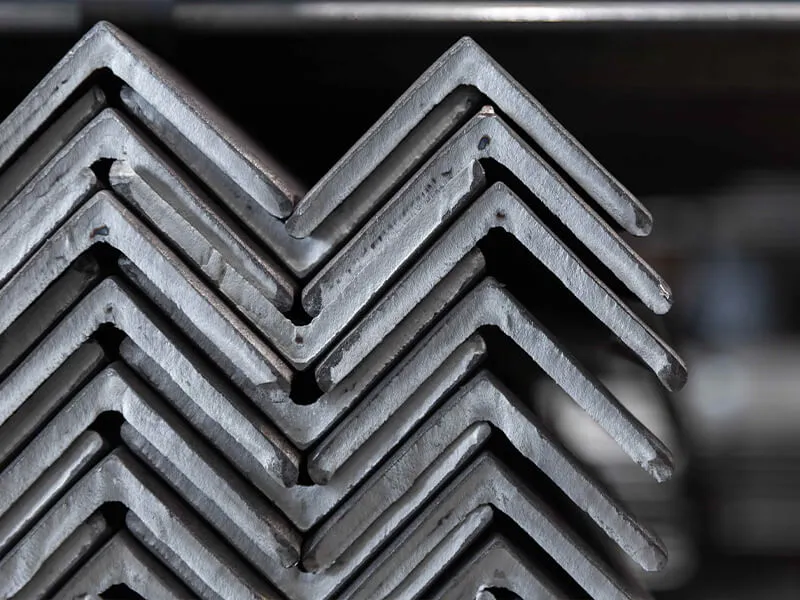
I spend a lot of my week answering drilling and machining questions from buyers in Vietnam, Qatar, and Saudi Arabia. Most of those conversations are not about the steel itself. They are about holes: where the pattern comes from, which leg it lands on, and why a stiffener that measured perfect on delivery suddenly will not bolt up. Drilling is the first step that destroys information instead of adding it. Once the bit cuts through a heat-number stamp or a gauge line lands 3 mm off, the certified bar in your shop has lost part of its identity, and no amount of skill at the drill press gets it back. So the checks that matter are all front-loaded, before the first hole. Below I walk through the four checkpoints our fabrication customers run: the drawing and hole pattern, the material and its markings, the setup on the machine, and the first-hole quality gate. Follow them in order and the drilling itself becomes almost boring, which is exactly what you want on a production schedule.
Which Drawing and Hole Pattern Details Must Be Confirmed First?
Hole patterns look simple on paper. But gauge lines, clearances, and hole categories differ between EN, ASTM, and GB projects. One wrong assumption locks the error into every stiffener.
Confirm the drawing revision, bolt diameter, hole category, and gauge line dimensions in writing before drilling. Hole diameter equals bolt diameter plus clearance: 1 mm for M12 and M14, 2 mm for M16 to M24, and 3 mm for M27 and larger under EN 1090-2 normal round holes.
Read the Hole Category Before the Diameter
The most common mistake I see is a buyer who treats “hole size” as one number. It is not. EN 1090-2 defines four categories of holes, and each category has its own clearance over the bolt shank. Normal round holes take 1 mm clearance for M12 and M14 bolts, 2 mm for M16 through M24, and 3 mm for M27 and above. Oversized round holes, short slotted holes, and long slotted holes each have their own table, and a long slotted hole is 2.5 times the bolt diameter in the slotted direction. The direction of a slot matters too: a short slotted hole is standard clearance across the axis of the member and elongated along it, so swapping the orientation silently changes how the connection resists load. I have seen quote requests that say “18 mm holes for M16” when the connection actually calls for a standard 18 mm hole, and I have seen others where the yard assumed 18 mm and the drawing meant a 20 mm oversize hole to absorb erection tolerance. Either assumption produces a hole that a bolt physically fits, which is why this error survives first inspection and only appears at assembly. Get the category named on the drawing or confirmed by the designer in writing. If your fabrication shop or our mill drills the holes for you, put the category on the work instruction, not just the diameter.
Set Out From a Datum, Not From the End of the Bar
The second pattern-level check is about measurement discipline. On an angle bar, every hole position should be measured from one fixed datum: the back of the heel (the outside corner of the angle) and one end face. Measuring each hole independently from an outside edge, or from the nearest toe, stacks small tape errors into a cumulative drift across the group, and the mating part will not drop in even though every individual hole “looks right”. Standards help you here. EN 1090-2 specifies zero negative tolerance on hole position measured from the end of a member, which means the first hole from the end can never be short of the drawing position. Minimum edge and end distances (back marks) come from the connection design rules in EN 1993-1-8, and for fatigue-sensitive structures EN 1993-1-9 calls for larger values. A widely used shop practice is to dimension holes at least 5 mm further from the edge than the minimum, so small setup errors still leave you inside the design envelope. On repetitive members, decide the drilling method before production: individual marking and drilling is only reliable for small isolated groups, while match marking, hardened-bush templates, or CNC drilling keep identical stiffeners interchangeable. My rule of thumb: if more than a dozen identical parts share a pattern, do not let anyone set it out by hand twice.
| Hole category (EN 1090-2) | M12 / M14 | M16 – M24 | M24 | M27 and larger |
|---|---|---|---|---|
| Normal round hole clearance | 1 mm | 2 mm | 2 mm | 3 mm |
| Oversize round hole clearance | 2 / 4 mm | 4 mm | 6 mm | 8 mm |
| Short slotted clearance (slot axis) | 4 mm | 6 mm | 8 mm | 10 mm |
| Long slotted hole | d0 = 2.5 × d in the slotted direction |
How Should You Verify the Material and Its Marking Before Cutting Into It?
Drilling destroys the evidence a surveyor needs. Once a hole cuts through a heat-number stamp, matching that stiffener to its mill test certificate becomes guesswork and classification surveys get harder.
Check that the heat number on each marine angle steel bar matches the mill test certificate, confirm the grade marking before any cutting, photograph the markings, and plan hole positions so stamps stay outside the drilled and welded zones.
Match the Steel to the Certificate While the Marking Is Still Visible
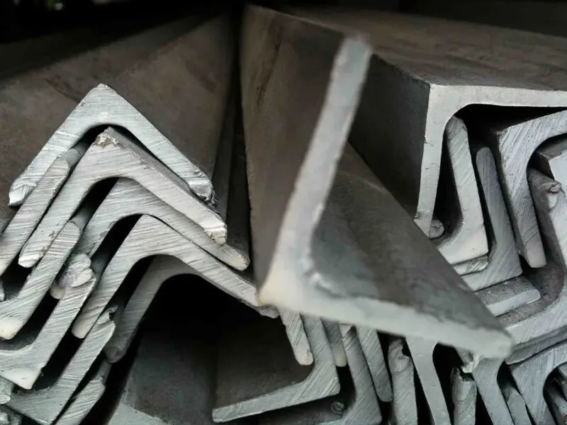
This check costs five minutes and saves arguments that last weeks. Walk along the bundles before anything is cut or drilled. Find the stamped or rolled marking on each piece: heat number, grade (for example AH36), and size. Compare it against the mill test certificate that shipped with the batch. The heat number on the steel must match the heat number on the certificate exactly. If it does not, stop the job, because the certificate may not belong to that material at all. Then photograph the markings and file the photos with the certificate. Once a stiffener is cut to length, drilled, and welded into a frame, the surveyor who wants proof of grade will look for that marking, and if drilling or grinding removed it, you are into traceability paperwork instead of pointing at a stamp. At our yard-side inspections with third-party agencies like SGS, this document-to-metal match is always the first gate, and the Gulf Metal Solutions shipment we handled to Dammam port cleared it before the container was even sealed. Plan the work order so that hole patterns and cut lengths never pass through the marking zone. A hole 20 mm from the heel at mid-length is fine; the same hole dropping onto the stamp at the bar end is a small decision with a large paperwork cost.
Check the Section Geometry Where the Holes Will Land
Material checks are not only about grade. Drilling amplifies any geometry problem the bar already has. Measure leg thickness at several points, including where the hole pattern sits, because a leg at the bottom of its thickness tolerance changes bearing area and clamp-up. Roll a straightedge along the leg to catch bow or twist: EN 10056-2 allows only limited straightness deviation, and a crooked bar that is force-clamped flat for drilling springs back afterwards and drags the holes off the mating line with it. Look at the root fillet where the two legs meet. A hole positioned over the fillet region forces the drill to cut through a transition zone where the bit tends to wander, and the resulting hole can be out of round or off perpendicular. Keep the pattern on the flat of the leg, clear of the root radius. Grade matters for the tooling plan as well: a normal-strength grade A and a high-strength AH36 both drill fine with sharp high-speed-steel bits, but AH36 rewards lower feed pressure and more generous cutting fluid. I keep repeating one line to customers: drilling is the cheapest process to check and the most expensive to undo, because the material you drilled is already certified and already paid for.
| Check before drilling | Tool | Red flag |
|---|---|---|
| Heat number vs MTC | Photo, certificate, marking | Numbers do not match |
| Grade marking (e.g. AH36) | Visual, stamp | Faded, ground off, or missing |
| Leg thickness at hole zone | Caliper, micrometer | Under tolerance at pattern area |
| Bow / twist of the bar | Straightedge, surface table | Beyond EN 10056-2 straightness limits |
| Root fillet clearance | Pattern drawing overlay | Hole falls on the root radius |
What Setup Checks Stop a Perfect Hole Landing in the Wrong Place?
Most drilling defects are not drill defects. They are setup defects: the wrong face, the wrong datum, or an unclamped bar that walks away from the bit mid-hole.
Set up with the angle oriented so holes land on the correct leg and face, clamp the section rigidly, measure every hole position from one fixed datum, keep holes clear of the root fillet, and hold at least 1.2 bolt diameters of edge distance.
Orientation: the Angle-Section Trap
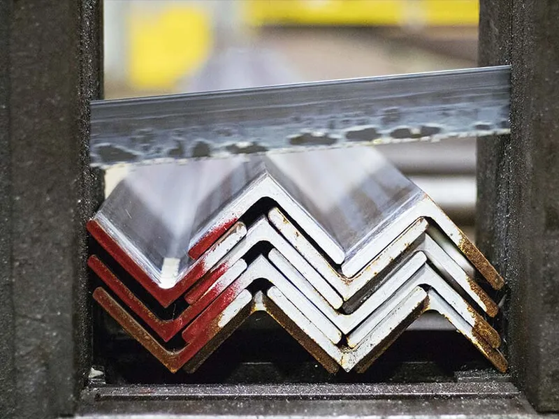
An angle is an asymmetric section, and asymmetry is where setup errors breed. With unequal-leg angles, the obvious failure is drilling the pattern on the wrong leg: 90 mm leg instead of 75 mm, holes one gauge line off before the bit even turns. The less obvious failure happens with equal legs. A hole pattern referenced to the heel reads differently from one referenced to the toe, and the same pattern drilled from the wrong reference lands closer to the toe than the drawing intends, thinning the edge distance. Connection faces matter too. If the stiffener bolts to a bracket face on one side, the burr side and the datum side both have a “correct” answer, and a pattern drilled on the wrong face may still fit the bolt but present the burrs to the faying surface. I watched a fabrication crew once set out a full batch of frame stiffeners from the first bar they drilled; the reference was taken off the toe instead of the heel, and every bar in the bundle inherited the error. Nothing about those holes looked wrong in isolation. The batch only failed when the first assembly refused to close. That afternoon cost them the drilling, the material, and two days of schedule, and it started with one reference decision at setup.
The Root Fillet, Edge Distance, and Clamping
Three geometric limits govern where a hole may live on the leg. First, keep the hole clear of the root fillet, as covered above: the pattern needs the flat of the leg, and the drawing’s gauge line already respects this if it is followed exactly. Second, respect edge distance. A commonly used minimum is 1.2 times the bolt diameter from the hole centre to the plate edge, and design rules add their own back-mark minimums measured from the back of the angle. Remember the shop practice of adding roughly 5 mm beyond the minimum so that normal setup tolerance does not eat into the design margin. Third, clamp the work rigidly and support it under the hole. An angle bar that can rock or vibrate lets the bit start on centre and finish off it, and the exit burr tears instead of shearing. Use a centre punch at every hole position so the bit has a seat, and drill on a flat, supported surface rather than across an open vise jaw. Finally, verify the first set-out against the drawing before the batch runs: check member mark, drawing revision, hole category, and which face carries the pattern. Two minutes with the drawing next to the clamped bar is the cheapest inspection in the whole process.
| Setup check | What goes wrong without it |
|---|---|
| Correct leg and face orientation | Pattern lands on the wrong leg; holes one gauge line off |
| Datum from the heel and one end | Cumulative drift across the hole group |
| Root fillet clearance | Bit wander at the root; out-of-round holes |
| Edge distance ≥ 1.2 × bolt diameter | Edge tearing; reduced bearing capacity |
| Rigid clamping with support | Hole drift, torn exit burrs, off-perpendicular axis |
| First set-out verified against drawing | Whole batch inherits one setup error |
What Hole Quality Should You Accept at the First Hole?
The first hole decides the batch. Inspect it like a first article: diameter, roundness, burrs, and axis. Accept it, and the rest of the pattern follows the same recipe.
Treat the first hole as a first-article check: verify diameter within the specified clearance, a burr-free rim, a round profile, and a perpendicular axis. Pilot-drill holes above 8 mm and use cutting fluid to protect both the bit and the hole wall.
The Pilot Hole and Cutting Fluid Routine
For holes larger than about 8 mm (5/16 inch), do not take the full diameter in one pass. Drill a pilot hole roughly one third of the final diameter first, then open up to size. The pilot keeps the large bit from skating across the rolled surface and reduces the thrust your machine and clamp have to resist. Use a sharp high-speed-steel bit, run at a moderate speed, and apply cutting fluid at the point; add more when you see smoke, because a blueing bit is losing hardness with every second and the heat is also work-hardening the hole wall you are trying to finish. Feed steadily rather than forcing: marine angle steel in the common 5 mm to 20 mm thickness range cuts cleanly with moderate pressure, and forcing the bit just produces heat, a tapered hole, and a shortened tool life. At the first hole, stop and measure. Check the diameter against the clearance you confirmed in the drawing review, check roundness by rotating a gauge pin, and check that the axis is perpendicular to the leg face. A slanted hole hides until the bolt goes through at an angle and the nut does not seat flat. Accept this first article, then lock the recipe: same bit, same speed, same feed, same fluid, same clamp, for the whole batch.
Burr Removal Is Not Optional
A burr looks harmless and behaves like a defect. Burrs on the faying surfaces prevent the connected plies from seating flush, so the joint carries load over burr contact points instead of the designed bearing area, and preloaded bolts lose part of their clamp because the plies never close. Burrs also interfere with hot-dip galvanizing and with paint coverage over the hole rim, which is exactly where corrosion starts on a ship. Deburr every hole before the section leaves the drilling station, and check the exit side, not just the entry side, because the exit burr is usually the larger one. A quick chamfering tool or a countersink pass at low speed finishes the rim cleanly. While you are at the hole, look at the rim condition: torn or work-hardened rims, and out-of-round holes, are the signature of a dull bit or excessive feed, and they get worse through the batch as the bit wears. If hole three looks worse than hole one, change the bit; do not push the batch to the end and inspect afterwards.
When Holes Do Not Line Up: Drifting Has Limits
Sooner or later a crew meets a hole group that is 1 or 2 mm out from the mating part, and someone reaches for a drift pin to force alignment. Standards allow alignment work, but they bound it: EN 1090-2 places limits on the elongation that drifting may produce, because a hole belled out by force has damaged its rim, lost bearing contact, and on fatigue-sensitive connections it can seed a crack. The disciplined sequence is to bring the plies together with close-fitting tapered drifts so bolts may be inserted freely, and to treat any hole that needs more than minor drifting as a non-conformance to review, not a production problem to muscle through. If misalignment is recurring rather than occasional, the fix is upstream: a hardened-bush template for repetitive patterns, match marking for complex geometry, or moving the pattern to a CNC drilling line. On our side, when a customer’s yard drills our angle steel, we prefer to supply the sections in the lengths and quantities that match a single drilling jig rather than mixed lengths, because one jig and one recipe keep every stiffener interchangeable. It is a small coordination step, and it removes most of the occasions when drifting is even tempting.

| Result comparison | Rushed drilling | Checked drilling |
|---|---|---|
| Hole category confirmed in writing | Assumed, sometimes wrong | Named on the work instruction |
| Datum and orientation | Toe-referenced, batch-inherited error | Heel datum, correct leg and face |
| Material markings | Drilled through, traceability lost | Photographed and preserved |
| First hole | Batch runs to the end, then inspection | First-article gate before the batch |
| Burrs | Left in place, faying surfaces stand off | Deburred entry and exit |
| Fit-up at assembly | Forced alignment, drifting damage | Bolts insert freely, plies close |
Conclusion
Drilling is quick. Undone drilling is not. Ten minutes of checks on drawings, markings, setup, and first-hole quality protects certified marine angle steel, bolt fit-up, and your delivery schedule.
Questions about hole patterns, gauge lines, or drilling-grade selection for your next angle steel order? Reach us at contact our export team, or browse our marine angle steel stock and bulb flat steel profiles for the sections behind most stiffener work.