You need a steel section with a 90-degree angle. Do you choose a standard angle bar or an L-shaped profile? The wrong choice can lead to a weak joint, wasted material, or a failed inspection.
L-shaped steel and angle bar often refer to the same product: a hot-rolled steel section with two perpendicular legs. The key difference is in application: "angle bar" is the general term, while "L-shaped steel" often implies a specific marine-grade product with tighter tolerances and classifications for shipbuilding frames and brackets.
Many buyers use these terms interchangeably, but in the marine industry, subtle distinctions matter. Choosing the right profile affects your project’s strength, cost, and compliance. Let’s compare them directly and explore the bigger picture of steel section selection.
What is the difference between angle bar and L bracket?
You see both terms on a drawing. An "L 100x75x8" might be called an angle bar in one note and an L bracket in another. This confusion can delay your order if you’re not sure what the designer intended.
An angle bar is the standard name for the raw, hot-rolled L-shaped steel section. An L bracket typically refers to a fabricated component made by cutting and sometimes welding angle bars (or other sections) to create a specific connecting piece for joining two members at a right angle.
Raw Material vs. Fabricated Part: Clarifying the Terminology
This question highlights a common mix-up between a material and a finished part. In my daily conversations with clients, clarifying this saves time and prevents errors. Let’s break it down clearly.
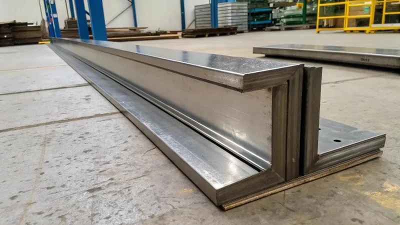
Angle Bar (or Angle Iron): The Raw Material
This is what we supply. It is a long, straight length of steel with a constant L-shaped cross-section. It is produced by hot-rolling in a mill. Its characteristics are:
- Standard Product: It is bought by the meter or ton, like any other steel section (I-beam, channel).
- Primary Use: It serves as a structural member. It can be a frame, a stiffener, a support leg, or a rail.
- Identification: It is defined by its leg dimensions and thickness:
L A x B x t(e.g., L 150x100x12 means one leg is 150mm, the other 100mm, and both are 12mm thick). - Surface: It typically has mill scale (a dark oxide layer) and may need shot blasting before painting.
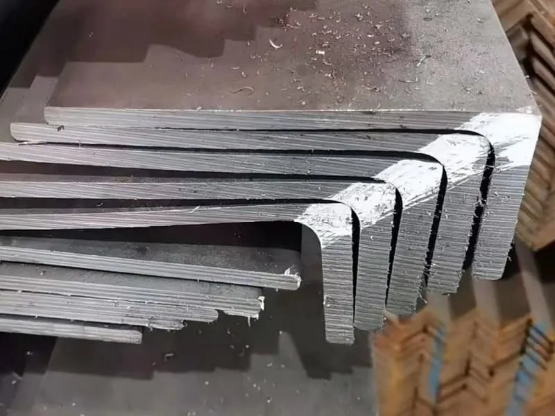
L Bracket: The Fabricated Component
This is something a workshop makes. It is a specific part cut from a longer angle bar (or plate) and prepared for installation.
- Fabricated Item: It is a finished piece, often part of a larger assembly drawing.
- Primary Use: It is specifically designed to connect two other pieces, usually at a 90-degree angle. Think of a shelf bracket.
- Identification: It is defined by its function and its detailed drawing, which specifies cut lengths, hole drilling, weld preparations, and sometimes additional welding.
- Surface: It is often fully fabricated (cut, drilled, welded) and then painted or galvanized as part of an assembly.
Here is a table to visualize the key distinctions:
| Aspect | Angle Bar (Material) | L Bracket (Component) |
|---|---|---|
| What it is | A standard, hot-rolled steel section. | A custom-fabricated connecting piece. |
| Origin | Produced in a steel mill. | Manufactured in a fabrication shop. |
| Form | Long, straight lengths (6m, 12m). | Short, specific lengths, often with modifications. |
| Typical Callout | L 100x100x10 (material grade optional). |
BRACKET, TYPE A, REF. DWG. 203 (with a detailed drawing). |
| Purchasing Question | "We need 5 tons of L 120x80x8mm in grade S355." | "We need 200 pieces of bracket P/N 4567, cut from 12mm plate, with 4x 20mm holes." |
| In the Supply Chain | We supply this to fabricators and shipyards. | Fabricators like Gulf Metal Solutions make these from the angle bar we supply. |
The "L-Shaped Steel" Nuance
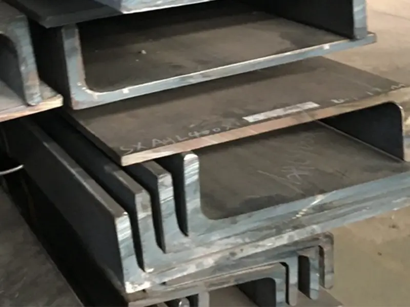
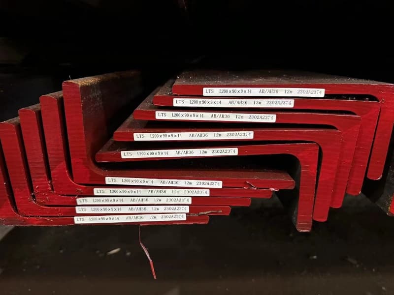
In marine contexts, "L-shaped steel" or "ship angle" sometimes refers to angle bars produced to stricter standards. These standards govern dimensional tolerances, straightness, and steel grade (like marine-grade AH36). They are essentially high-quality angle bars destined for critical ship structures. So, when a shipyard orders "L-shaped steel," they might be emphasizing the specification over the generic term "angle bar."
Understanding this difference streamlines communication. When you ask us for angle bar, we provide the raw material. If you need L brackets, we need the fabrication drawing to ensure we supply the correct raw material (dimensions, grade, condition) for your workshop to make them.
What are the disadvantages of using angle steel?
Angle bars are versatile and popular. But choosing them for the wrong application leads to weak structures, high cost, and fabrication headaches. Every material has trade-offs.
The main disadvantages of angle steel include lower torsional stability (it can twist easily), asymmetric load-bearing capacity depending on orientation, stress concentrations at the sharp re-entrant corner, and sometimes less efficient material use compared to closed sections for certain loads. It also requires careful connection design.
Understanding the Limits of the "L" Shape
Angle bars are not a universal solution. Their disadvantages stem directly from their open, asymmetric shape. As a supplier, I see projects where another section would have been better. Let’s analyze these drawbacks so you can make informed decisions.
1. Poor Torsional Resistance1
This is the biggest weakness. An angle bar’s cross-section is open and thin-walled. Imagine trying to wring out a towel by twisting it—it twists easily. An angle bar behaves similarly under torsional (twisting) loads.
- Consequence: If used as a beam where twisting is possible, it can fail unexpectedly. A simple example is a signpost made from a single angle; the wind can twist it.
- Mitigation: Use two angle bars back-to-back to form a "box" section, or choose a tube or hollow structural section (HSS) instead.
2. Asymmetric and Direction-Dependent Strength2
An angle bar is not equally strong in all directions. Its geometric axes (x-x and y-y) have different properties.
- Strong Axis: Bending an angle bar with the load applied perpendicular to one leg (so it bends "into" the corner) uses its strongest axis.
- Weak Axis: Bending it with the load applied parallel to a leg (so it tries to "open" the angle) uses its weaker axis. The strength difference can be significant.
- Consequence: You must install it in the correct orientation per the engineer’s drawing. A mistake during installation can drastically reduce its load capacity.
3. Stress Concentration at the Root3
The inside corner of the "L" is a sharp, 90-degree re-entrant corner. Under stress, this point becomes a focal area for stress concentration.
- Consequence: This can promote crack initiation under cyclic loading (fatigue), which is a critical concern in ship structures subjected to wave loads.
- Mitigation: Good fabrication practices, like using a generous weld fillet or sometimes grinding a small radius in the corner, can help reduce this risk.
4. Connection Complexity4
Connecting angle bars neatly can be challenging. Bolts or welds often must be placed off-center, creating eccentricities that induce secondary bending moments.
- Consequence: Connections require more careful design and can be more expensive to fabricate than connections for symmetric sections like I-beams.
5. Material Efficiency (Weight vs. Strength)5
For pure axial compression, a hollow tube uses material more efficiently than an angle bar of similar weight. The angle bar’s material is concentrated in two legs away from its center, which is not optimal for resisting buckling.
This comparison table shows when angle bars are suitable versus when alternatives might be better:
| Loading Scenario | Suitability of Single Angle Bar | Potential Better Alternative |
|---|---|---|
| Pure Tension (as a tie) | Excellent. Simple and effective. | None needed; angle bar is good. |
| Light Bending (Strong Axis) | Good for short spans, light loads. | Channel section for more stability. |
| Bending (Weak Axis) | Poor. Very inefficient. | Use two angles back-to-back or a tube. |
| Heavy Bending / Major Beam6 | Not ideal. | I-beam or Wide Flange beam. |
| Axial Compression (Column) | Acceptable for short lengths. Prone to buckling. | Hollow Structural Section (HSS) or built-up column. |
| Applications with Torsion7 | Very Poor. | Circular or rectangular hollow section. |
| Typical Marine Use8 | Excellent as secondary stiffeners, brackets, small frames. | Bulb flats for primary longitudinal stiffeners. |
Knowing these disadvantages helps you have better conversations with engineers and fabricators. It also explains why marine designs use a mix of sections: bulb flats for main hull stiffeners (better bending efficiency), and angle bars (L-shaped steel) for frames, brackets, and other secondary structures where their ease of welding and handling is an advantage.
What is the strongest steel beam shape?
"Strongest" is a vague term. Do you mean strongest in bending? Strongest in compression? Or strongest per unit weight? The answer changes based on the question, and the best shape is often a compromise.
There is no single "strongest" shape for all situations. For resisting bending (flexure), an I-beam or Wide Flange beam is typically the most efficient shape. For pure axial compression, a circular hollow section is often strongest against buckling. The "strength" depends on the load type and the material’s distribution around the section’s neutral axis.
Defining "Strength": A Contest of Efficiency
The quest for the strongest beam is really a quest for the most efficient shape. Efficiency means achieving the highest load capacity with the least amount of material (weight). The key metric here is the Section Modulus for bending and the Radius of Gyration for buckling.
Strength in Bending: The Reign of the I-Beam
When a beam bends, the material farthest from the center (neutral axis) experiences the highest stress. An efficient shape puts most of its material as far away from the center as possible.
- I-Beam/Wide Flange: This shape is brilliant for bending. It has thick flanges at the top and bottom (far from the center) to handle the tension and compression. It has a thinner web in the middle, which is mainly there to hold the flanges apart and resist shear. This uses material almost perfectly for its job.
- Comparison: For the same cross-sectional area (weight per meter), an I-beam will have a much higher Section Modulus (S) than a solid rectangle, a circle, or an angle bar. This means it can carry a much larger bending moment before failing.
Strength in Compression (Column): The Power of the Tube
When a member is squashed (in compression), the main failure mode is buckling. Resistance to buckling depends on how the material is distributed in all directions, measured by the Radius of Gyration (r).
- Circular Hollow Section (CHS): A pipe has material distributed uniformly around its center. It has equal and high radii of gyration in all directions. This makes it exceptionally good at resisting buckling from any angle, making it the "strongest" shape for a pure column.
- Square/Rectangular Hollow Section (SHS/RHS): Also excellent for columns and offers flat surfaces for easier connections.
The Compromise Shapes
Real-world beams often experience combined bending, compression, and torsion.
- Box Sections (built-up or hollow): Excellent for combined bending and torsion (e.g., crane girders).
- Channels and Angles: Less efficient than I-beams for pure bending but offer other advantages like ease of connection or fitting into tight spaces.
Let’s compare profiles for two different definitions of "strongest":
| Profile Shape | Best For… | Key Strength Metric | Why It’s "Strong" | Marine Application Example |
|---|---|---|---|---|
| I-Beam / Wide Flange | Strongest in Bending (per unit weight). | High Section Modulus (S). | Concentrates material in the flanges, far from the neutral axis. | Large deck beams, transverse frames in large vessels. |
| Circular Hollow Section (Pipe) | Strongest Column (resists buckling). | High & Equal Radius of Gyration (r). | Material is uniformly distant from the center in all directions. | Mast supports, structural pillars. |
| Box / Hollow Section | Strong in Bending & Excellent in Torsion. | High Torsional Constant (J). | Closed shape provides continuous path for shear flow. | Crane booms, special reinforced structures. |
| Bulb Flat | Strong in one-direction bending when attached to a plate. | Efficient as a stiffener. | Works compositely with the hull plate, forming a T-beam. | Primary longitudinal stiffeners on hull and deck. |
| Angle Bar (L-Shape) | Not the "strongest" in a general sense. | Good strength-to-weight for specific uses. | Versatile, easy to fabricate and connect. | Secondary frames, brackets, supports (as L-shaped steel). |
So, L-shaped steel (angle bar) is not the "strongest" beam. Its value lies elsewhere: in its versatility, ease of fabrication, and effectiveness in specific roles like bracing and bracketing. You choose it not for ultimate strength, but for the right balance of strength, cost, and constructability.
What is the best beam shape for bending?
You need a beam to span an opening and carry a load. You want it to be stiff, strong, and light. The shape you choose dramatically affects performance and cost. The "best" shape maximizes stiffness and strength while minimizing material.
The best steel beam shape for resisting bending forces is an I-beam or Wide Flange beam. Its design places most of the material in the top and bottom flanges, far from the neutral axis, which maximizes the Section Modulus. This makes it the most efficient and cost-effective shape for pure bending applications like building girders and major ship frames.
Engineering Efficiency: How Shape Deflects Load
Bending causes one side of a beam to stretch (tension) and the other to squash (compression). The core principle is that stress increases with distance from the beam’s central "neutral axis." Therefore, the best shape puts as much material as possible at the greatest distance from this axis.
The I-Beam: The Benchmark for Bending
Let’s analyze why it’s so effective:
- Flanges: The horizontal top and bottom parts carry almost all the bending stress. They are thick and wide to provide a large area far from the center.
- Web: The vertical part connects the flanges. It is relatively thin because its main jobs are to resist shear force and prevent the flanges from moving together. It adds little to the bending resistance but does so with minimal material.
- Efficiency: For a given amount of steel (cross-sectional area), an I-beam configuration achieves a higher Section Modulus (S) and Moment of Inertia (I) than a solid rectangle of the same height and area. A higher "I" means less deflection (more stiff). A higher "S" means it can carry more load before yielding (more strong).
Comparing Other Shapes for Bending
- Solid Rectangular Bar: Very inefficient for bending. Much of the material near the neutral axis is under low stress and is essentially "wasted." It is heavy for the strength it provides.
- Channel (C-Shape): Good for bending in one direction (strong axis), but the flanges are only on one side of the web. This makes it asymmetrical and susceptible to twisting (torsional buckling) if not properly restrained.
- Angle Bar (L-Shape): Poor as a primary bending beam on its own. Its material is not optimally distributed. However, two angles bolted or welded back-to-back can form a respectable beam for lighter loads.
- Box/Hollow Section: Excellent in bending, nearly as good as an I-beam for the same depth, and superior in torsion. However, it can be more expensive to fabricate than a rolled I-beam.
- Bulb Flat: This is a special case. On its own, it’s like a T-beam and is not efficient. But in shipbuilding, it is continuously welded to a steel plate. Together, they form a combined T-beam where the plate acts as the massive top flange, and the bulb flat acts as the web. This composite system is extremely efficient for stiffening large plate panels—it’s the "best" shape for that specific application.
This decision matrix helps select a shape for bending:
| Design Priority | Recommended Shape(s) | Reason | Practical Consideration |
|---|---|---|---|
| Maximum Bending Efficiency (Least weight for strength) | Wide Flange I-Beam (W-shape). | Highest section modulus for the material used. | The standard choice for beams and girders in construction and large ship frames. |
| Bending + Torsion / Aesthetics | Square or Rectangular Hollow Section (SHS/RHS). | High bending strength and excellent torsional resistance. Clean appearance. | Used for exposed structures, railings, crane girders. |
| Bending + Attachment to a Plate | Bulb Flat (combined with plate). | Forms an efficient integral T-beam with the attached plate. | The universal choice for hull and deck longitudinal stiffeners in ships. |
| Light Bending + Easy Connections | Channel Section (C-shape). | Good strong-axis bending, easy to bolt or weld to. | Used for purlins, small framing, and supports. |
| Bending on a Budget for Very Small Spans | Angle Bar (double back-to-back). | Low cost, readily available, can be fabricated into a beam. | Used for light support frames, platforms, and non-critical structures. |
Where does L-shaped steel fit in? It is rarely the "best beam for bending." Its role is different. It is the "best" for creating 90-degree connections (brackets), for short-span bracing, and for applications where its simplicity and ease of fabrication outweigh the need for maximum bending efficiency. When you understand this, you stop trying to use an angle bar as a main beam and start using it for what it excels at.
Conclusion
L-shaped steel (angle bar) excels in versatility and fabrication, not as the strongest or best bending beam. Choose I-beams for major bending, tubes for columns, and angle bars for their specific strengths in connections and secondary structures.
-
Understanding torsional resistance is crucial for structural integrity; explore this link to learn how to mitigate risks. ↩
-
Discover the implications of asymmetric strength on design choices and load capacities in this insightful resource. ↩
-
Learn about stress concentration and its impact on structural performance, especially in cyclic loading scenarios. ↩
-
Explore the complexities of angle steel connections and how to design them effectively for better performance. ↩
-
Gain insights into material efficiency and its importance in selecting the right structural components. ↩
-
Find out which materials outperform angle steel in heavy bending scenarios for safer and more efficient designs. ↩
-
Learn about the best structural alternatives to angle steel for torsional applications to enhance safety and performance. ↩
-
Explore the various applications of angle steel in marine environments and their advantages in structural design. ↩