You have the best materials—premium bulb flats and precise marine angle steel—arriving on time from your supplier. But if your joining methods are weak or incorrect, you are building hidden weaknesses into the ship’s skeleton. I have seen projects where perfect materials failed in fabrication because the connection details were an afterthought. This is a critical moment. The strength of a hull is not just in the steel itself, but in the integrity of every single joint.
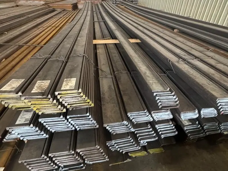
To combine bulb flat and angle steel in hull construction, you primarily use welding. The bulb flat’s rounded edge is typically welded to the hull plate. The angle steel is then welded to both the bulb flat’s flat face and the plate, creating a rigid, T-shaped stiffener assembly. Proper joint design, weld sequence, and strict adherence to marine welding procedures are essential to prevent distortion and ensure structural integrity.
Understanding the principle is one thing. But to execute it flawlessly in a noisy, demanding shipyard environment, you need to master the fundamentals of joining metal. Let’s start with the most basic question and build up to the complex reality of assembling a ship’s frame.
How to join two thin pieces of metal?
Think about the thin plating of a ship’s superstructure or internal bulkheads. A weak joint here can lead to leaks, cracks, and noise. The challenge is to create a strong bond without burning through the material or causing severe warping. In my early days visiting fabrication shops, I often saw thin metal joined poorly. The welds looked messy, and the panels were distorted like potato chips. This directly affects the fit-up of subsequent parts and the final quality of the vessel.
To join two thin pieces of metal, the most common and effective method is welding, specifically Gas Metal Arc Welding (GMAW/MIG) or Gas Tungsten Arc Welding (GTAW/TIG)1. These processes allow for precise heat control2. Using a lower current, faster travel speed, and sometimes a backing strip3 are crucial techniques to prevent burn-through4 on thin sections.
Diving Deeper: Techniques and Considerations for Thin-Gauge Joining
Joining thin metal is a test of a welder’s skill and the suitability of the process. It’s not just about making a weld; it’s about managing heat input.
Why Heat Control is Everything
Steel is a good conductor of heat. With thin metal, there is very little material to absorb and dissipate the welding arc’s intense heat. Excessive heat has two major negative effects:
- Burn-Through: The heat melts a hole completely through the workpiece. This creates a defect that requires repair, adds time, and weakens the joint.
- Distortion: Metal expands when heated and contracts when it cools. Uneven heating and cooling causes the thin sheet to warp, bend, and buckle. This distortion5 makes it impossible to achieve the flat, true surfaces required in shipbuilding.
Choosing and Applying the Right Process
Different welding processes offer different levels of control. For shipbuilding applications on thinner plates (typically below 6mm), here are the primary options:
| Process (Common Name) | How It Works | Best For Thin Metal Because… | Key Challenge to Manage |
|---|---|---|---|
| GTAW (TIG) | Uses a non-consumable tungsten electrode. Filler metal is added separately. | It provides the most precise arc and heat control2. The welder can finely adjust the amperage. It produces very clean, high-quality welds. | It is a slower process. It requires a high level of operator skill. It is less suitable for very long seams in production. |
| GMAW (MIG) | Uses a continuously fed consumable wire electrode. Shielding gas protects the weld. | It is faster than TIG. The equipment is easier to use. Modern pulsed MIG settings offer good control over heat input. | The higher deposition rate can still lead to too much heat if settings are wrong. It requires good access to the joint. |
| Spot Welding (Resistance) | Uses electrodes to clamp the metal and pass a large current, creating a melt nugget. | It is extremely fast for lap joints. It concentrates heat in a tiny spot, minimizing overall distortion5. | It only creates intermittent connections, not a continuous seal. It is mainly for lap joints, not butt joints. It requires specific, often heavy, equipment. |
Practical Tips for Success
Beyond choosing the process, welders use specific techniques for thin metal:
- Use a Backing Strip: A copper bar or ceramic strip placed behind the joint helps sink away excess heat and supports the molten weld pool to prevent sagging or burn-through4.
- Employ a Stitch or Skip Welding Technique: Instead of welding a long seam continuously, you weld a short section (e.g., 2 inches), skip a gap (e.g., 4 inches), weld another section, and so on. This allows heat to dissipate in the skipped areas, drastically reducing distortion5. You later go back and fill in the gaps.
- Clamp Everything Securely: Using strong clamps and tack welds at intervals holds the pieces in the correct position and alignment, fighting the forces of thermal expansion and contraction.
Mastering thin metal is the foundation. The next step is connecting the heavier structural members that give the ship its shape.
How to connect two metal bars together?
Now we move from sheets to bars—think of angle steel legs or small bulb flats used as stiffeners. The connection must handle shear forces and bending moments. A simple butt joint is often not enough. I remember a contractor showing me a failed bracket. Two angle bars were joined end-to-end with a small weld. The joint snapped under load because it was designed like a decoration, not a structural component. The connection method must match the force it will bear.
To connect two metal bars together for structural purposes, common methods include welding with full-penetration butt welds1 or fillet welds2 on lapped or T-joints, and mechanical connections using high-strength bolts3 through drilled holes. The choice depends on the required strength, whether the connection needs to be disassembled, and the available access for tools.
Diving Deeper: Structural Connections in Marine Fabrication
In hull construction, bars are not just connected; they are integrated into a load-bearing framework. The goal is to transfer stress efficiently from one member to another without creating a weak point.
Welded Connections: Creating a Monolithic Structure
Welding is the primary method for permanent, high-strength connections in shipbuilding. For connecting bars, the joint preparation is key.
- Butt Joints: Used when two bars need to be joined end-to-end in a straight line (e.g., lengthening a stiffener). For full strength, the ends are often beveled to create a V- or U-groove. This allows the weld metal to penetrate through the entire thickness of the bar, creating a "full penetration" weld that is as strong as the base metal itself.
- Fillet Welds in Lap and T-Joints: This is extremely common. When one bar sits on top of another (lap joint) or meets it at a right angle (T-joint), fillet welds2 are placed along the edges of the intersection. The size of the fillet weld (the leg length) is calculated by naval architects to withstand the specific loads at that location.
Bolted Connections: For Assembly and Access
While less common in primary hull welding, bolting is vital in specific scenarios:
- Temporary Connections during Assembly: Large blocks may be bolted together at the dock before final welding.
- Connections that Require Future Disassembly: Equipment foundations, access panels, or non-critical secondary structures might be bolted for maintenance access.
- Field Connections in Repair Work: Bolting is sometimes used in repair scenarios where welding is difficult or risky.
High-strength bolts (e.g., Grade 8.8 or higher) are used. The holes are drilled or punched precisely. The connection’s strength comes from the clamping force of the tightened bolts, which creates friction between the joined pieces, and the shear strength of the bolt shank.
The Critical Factor: Stress Concentration and Fatigue
Any connection is a potential point of failure. A sharp corner, a small weld toe, or a poorly drilled hole can concentrate stress. In a ship, which flexes constantly in waves, this concentrated stress can initiate a fatigue crack that grows over time. Therefore, good practice is essential:
- Welds must have a smooth transition to the base metal (good "weld toe" profile).
- Bolt holes must be deburred and clean.
- Connection details should avoid sudden changes in stiffness.
With the basics of bar connections covered, we need to focus on the most common welding position and its critical variable: the work angle.
When welding in the flat position, you should have a work angle1?
Every welder loves the flat position (1G/1F). It’s easier, faster, and gravity helps. But "easier" does not mean "thoughtless." I’ve seen inspectors fail perfectly good welds because the work angle1 was wrong, leading to poor fusion on one side of the joint. The angle of your torch or electrode is not a minor detail; it directly controls where the heat goes and where the molten metal is deposited. Getting it wrong creates a weak bond hidden inside what looks like a good weld.
Yes, when welding in the flat position, you must maintain a correct work angle1. The work angle1 is the angle of the welding tool relative to a line perpendicular to the workpiece. For a basic T-joint2 (fillet weld3), a typical work angle1 is 45 degrees between the two plates to evenly distribute heat and filler metal to both sides of the joint.
Diving Deeper: Mastering the Geometry of the Arc
The work angle1, combined with the travel angle4 (the angle along the direction of travel), is how a welder "aims" the welding arc. This aiming controls three fundamental things: penetration, bead shape, and defect prevention.
Understanding the Types of Angles
It’s important to distinguish between the two main angles a welder controls:
- Work Angle: As defined above. Think of it as the left-right tilt of the tool when looking straight down the weld joint.
- Travel Angle: Also called the drag or push angle. This is the angle of the tool along the line of the weld, relative to the vertical. A "drag" or "backhand" angle (pointing back toward the completed weld) typically gives deeper penetration. A "push" or "forehand" angle (pointing toward the unwelded area) gives a flatter, wider bead with less penetration.
How Work Angle Affects Specific Joints
The ideal work angle1 changes based on the joint geometry. Here is a guide for common situations in hull construction:
| Joint Type | Example in Hull Construction | Recommended Work Angle (Approx.) | Reason and Goal |
|---|---|---|---|
| Fillet Weld (T-Joint) | Angle steel welded to a hull plate. Bulb flat welded to a plate. | 45 degrees from horizontal, bisecting the angle between the two plates. | To direct equal heat to both the vertical and horizontal members. This ensures good fusion on both sides and creates a weld with equal leg lengths. |
| Lap Joint | Overlapping thin plates. | 30 to 40 degrees from the vertical, pointing towards the lower plate. | To ensure adequate penetration into the bottom plate, which is critical for strength. Too vertical an angle will put most heat into the top plate. |
| Groove Weld (Butt Joint) | Two hull plates edge-to-edge. | For V-grooves, often 5-15 degrees from vertical, depending on bevel angle. May oscillate side-to-side. | To ensure the arc reaches the root of the joint for full penetration and properly fills the groove on both sides without creating undercut5 (a groove melted into the base metal at the weld edge). |
| Multi-Pass Fillet Weld | A large stiffener connection requiring several weld layers. | Changes with each pass. First pass might be 45°. Later passes may be angled more toward the previous bead to remelt it and ensure fusion between passes. | To properly fill the joint and create a sound, monolithic weld structure without defects like lack of inter-pass fusion or slag inclusions. |
Consequences of Incorrect Work Angle
Ignoring work angle1 leads to predictable defects:
- Unequal Leg Length: On a fillet weld3, one leg is long, the other short. The effective throat (the shortest distance through the weld) is reduced, lowering strength.
- Lack of Fusion: The weld metal does not properly bond with one side of the base metal. This creates a hidden crack.
- Undercut: The arc gouges a groove into the base metal next to the weld, creating a sharp notch that is a prime starter for fatigue cracks.
- Excessive Spatter: Poor angle can lead to a less stable arc and more wasted metal droplets.
Now, let’s apply all these principles—thin sheet joining, bar connecting, and precise angle control—to the most fundamental act in shipbuilding: joining the massive steel plates that form the skin of the ship.
How to join two steel plates?
This is the grand scale application of everything we’ve discussed. The hull plate is the ship’s first line of defense. A seam failure here is not a repair; it’s a potential catastrophe. The joining of these plates is a meticulously planned industrial process. From supplying the plates to seeing them become part of a vessel, I know that every certificate, every beveled edge, and every weld procedure specification (WPS) matters. This is where theoretical knowledge meets tonnage of steel and the skill of the welding crew.
To join two steel plates in shipbuilding, the standard method is butt welding. The plate edges are prepared (beveled) to create a V, U, or X-groove. They are aligned and tack-welded. Then, welders execute multi-pass welds, often using submerged arc welding (SAW) for efficiency on flat sections, following a qualified Welding Procedure Specification (WPS) to ensure strength and toughness that matches the base plate.

Diving Deeper: The Marathon of Plate Butt Welding
Joining ship plates is not a single weld. It is a sequenced, layered construction process designed to build a joint that is as reliable as the parent metal.
Step-by-Step: From Fit-Up to Final Pass
-
Edge Preparation and Fit-Up: Plates from the mill have sheared or gas-cut edges. These edges must be machined or ground to the precise bevel angle specified in the design (e.g., 30° V-groove). The plates are then positioned on the bed or panel line with a strict root gap (the space between them). They are clamped and secured with strong tack welds. Accurate fit-up is critical; gaps that are too wide or narrow will cause problems during welding.
-
Backing and Root Pass: The first weld pass is the most critical. It must fuse the two plates at the root without defects. For one-sided welding, a backing strip (often of steel) is sometimes welded to the back side to support the root pass. Alternatively, skilled welders using specific techniques (like TIG root pass) can achieve a sound root without backing. This root pass must have complete penetration.
-
Filling and Capping Passes: After the root, the groove is filled layer by layer. Each pass is cleaned of slag (in processes like SMAW or SAW) before the next is applied. The work and travel angles are adjusted for each pass to properly fuse with the sidewalls and the previous weld bead. This continues until the groove is almost full.
-
The Cap Pass: The final layer is the cap pass. This weld is made with care to produce a smooth, slightly convex profile that blends well with the base plate. It must be free of cracks, porosity, and undercut, as it is the most exposed surface.
Processes Used in Shipyard Plate Welding
Different processes are chosen for their productivity and quality at different stages:
| Process | Typical Use in Plate Joining | Advantages | Disadvantages |
|---|---|---|---|
| Submerged Arc Welding (SAW) | Filling and capping passes on long, straight seams in the flat position (e.g., on panel lines). | Very high deposition rate. Excellent quality due to slag protection. No visible arc, so no need for helmets. Deep penetration. | Only for flat or horizontal positions. Requires handling of granular flux. Complex setup. |
| Shielded Metal Arc Welding (SMAW/Stick) | Root passes, short seams, out-of-position welding (vertical, overhead), and repair work. | Extremely versatile. Equipment is simple and portable. Works in all positions. Good penetration. | Slower. Produces slag that must be removed. Requires more operator skill for consistent quality. |
| Flux-Cored Arc Welding (FCAW) | Widely used for filling passes in all positions. Common in block assembly. | Higher deposition rate than SMAW. Good out-of-position performance. Deep penetration. | Produces more fumes. Can be more prone to porosity if parameters are wrong. |
| Gas Tungsten Arc Welding (GTAW/TIG) | Critical root passes on pipes or important seams where utmost quality is needed. | The highest quality, cleanest weld. Excellent control. No slag. | Very slow. Requires the highest operator skill. |
Quality Assurance: The Non-Negotiable Element
Every single plate weld is subject to rigorous inspection, often by both the shipyard and the classification society surveyor. This includes:
- Visual Inspection (VT): Checking for surface defects.
- Radiographic Testing (RT): Using X-rays or gamma rays to see inside the weld for voids, cracks, or lack of fusion.
- Ultrasonic Testing (UT): Using sound waves to find internal defects and measure weld penetration.
The Welding Procedure Specification (WPS) that guides all this work is a legal document. It is qualified by testing to prove that welds made by following it will meet the mechanical properties (strength, toughness) required for the ship’s hull.
Conclusion
Combining bulb flat and angle steel effectively comes down to mastering the basics: choosing the right joining method for the material thickness, applying precise welding angles, and executing plate connections with disciplined procedure. Strong materials demand equally strong joints.
-
Understanding work angle is crucial for achieving strong, defect-free welds. Explore this link to enhance your welding skills. ↩ ↩ ↩ ↩ ↩ ↩ ↩ ↩ ↩ ↩
-
Learn the best practices for welding T-joints to ensure strong and reliable connections in your projects. ↩ ↩ ↩ ↩ ↩
-
Discover essential techniques for fillet welding to improve your welding quality and efficiency. ↩ ↩ ↩ ↩
-
Understanding travel angle can significantly impact your weld quality. Explore this resource for in-depth insights. ↩ ↩ ↩
-
Preventing undercut is essential for weld integrity. This link offers strategies to avoid this common issue. ↩ ↩ ↩ ↩