A single design oversight in a marine platform can lead to catastrophic structural failure. The relentless ocean demands absolute precision, starting with the steel at its core.
Designing marine platforms with certified steel follows a strict process: defining loads and environment, selecting certified steel grades per class rules, detailed structural analysis, specifying material with full traceability, and ensuring fabrication meets approved welding procedures. The steel’s certification (e.g., DNV, ABS, EN 10225) is non-negotiable.
I’ve seen projects delayed for months because the steel certificates didn’t match the class society requirements. The design on paper is only as strong as the real metal you build with. Let’s walk through the entire journey, from the first calculation to the final bolt tightening.
How to design a steel structure step by step?
Designing a marine platform1 isn’t a single task. It’s a disciplined sequence. Jumping ahead without completing one step can force you to go back and start over, wasting huge amounts of time and money.
The design of a marine steel structure follows a systematic engineering sequence: 1) Define all loads and environmental conditions, 2) Select preliminary member sizes and certified steel grades2, 3) Create a detailed 3D model for global analysis3, 4) Perform local strength and fatigue checks, 5) Specify all materials and connection details, and 6) Produce fabrication drawings4.
This process turns a concept into a buildable, safe structure. Each step relies on the one before it. Let’s break down what happens in each phase, especially where certified steel becomes critical.
The Detailed Stage-Gate Process for Marine Structures
Marine design is governed by "stage-gate" reviews. You must pass one gate before moving to the next. This ensures safety and quality.
Phase 1: Pre-Engineering and Basis of Design
This is the foundation. Everything else depends on it.
- Site-Specific Data: Water depth, soil conditions, wave heights (100-year storm), wind speeds, current data, seismic zone, and ice loads if applicable. This data comes from marine surveys.
- Functional Requirements: What is the platform for? Oil production, gas compression, wind turbine support, or a living quarters? This defines the layout, equipment weights, and operational loads.
- Load Definition: The engineer lists every force the structure will see: Dead Load (its own weight), Live Load (people, equipment, supplies), Environmental Loads (wave, wind, current, earthquake), and Accidental Loads (boat impact, fire).
- Design Codes and Class Society: The project chooses the governing rules. This could be DNV GL, American Bureau of Shipping (ABS), API (American Petroleum Institute), or ISO 19900 series. This choice dictates the safety factors and material standards you must use.
Phase 2: Conceptual and Preliminary Design
Here, you create the first sketches and rough calculations.
- Selecting the Structural Type: Will it be a jacket (for shallow/moderate water), a floating system (TLP, SPAR, Semi-submersible), or a monopile (for wind turbines)? This major decision shapes everything.
- Preliminary Sizing: Using simplified models, engineers estimate the size of main legs, brace diameters, and deck beam sections.
- Initial Material Selection: Based on the loads and the chosen class rules, engineers select preliminary steel grades. For a jacket in the North Sea, they might default to DNV GL offshore steels like NV 420 or NV 460. The certification requirement is set here.
Phase 3: Detailed Design and Analysis
This is the core engineering work, done using advanced software like SACS, SESAM, or ANSYS.
- 3D Modeling and Global Analysis: A full computer model of the structure is built. The software applies all the defined loads and simulates the structure’s behavior. It checks for overall stability, deflection, and base shear.
- Member Code Checks: Each individual beam, column, and brace is checked against the design code. The software confirms that the chosen steel grade and section size can handle the calculated stresses (axial, bending, shear).
- Fatigue Analysis: This is critical for offshore. The software calculates stress ranges from millions of wave cycles over the platform’s life (e.g., 30 years). It identifies "hot spots" like welded joints that need special attention. Fatigue often governs the design more than ultimate strength.
- Specialized Analyses: Push-over analysis (for earthquakes), boat impact analysis, dropped object analysis, and fire and blast analysis for oil & gas platforms.
Phase 4: Material and Fabrication Specification
Now, the abstract model turns into a physical procurement list. This is where my world as a steel supplier directly connects.
- Material Take-Off (MTO): A detailed list of every piece of steel: plates, sections, tubes, with exact dimensions, grades, and weights.
- Purchase Specification: This document is sent to suppliers. It specifies not just the grade (e.g., EN 10225 S355G2+M), but also the required certification (e.g., "DNV GL Works Certificate Type 3.2"), impact test temperatures, through-thickness (Z) properties, delivery condition (Normalized or TMCP), and surface preparation.
- Connection Design: Detailed drawings for every weld, bolted connection, and complex node. This includes Welding Procedure Specifications (WPS) that must be qualified before fabrication starts.
Phase 5: Drawing Production and Review
The final shop drawings and construction drawings are produced. They are reviewed by the design team, the client, and the class society surveyor. Only after approval does fabrication begin.
| Design Phase | Key Activities | Critical Steel-Related Decisions/Outputs | Common Pitfalls Without Certified Steel |
|---|---|---|---|
| Basis of Design | Collect site data, define loads, choose codes. | Selection of governing material standard (e.g., DNV, API). | Choosing a code without available certified steel can halt procurement. |
| Preliminary Design | Choose concept, size main members. | Preliminary grade selection (e.g., "S355 offshore grade"). | Underestimating toughness requirements leads to wrong grade selection. |
| Detailed Analysis | Global/Local FEA, Fatigue analysis. | Final confirmation of grade and thickness for each member. | Analysis assumes certain material properties. Uncertified steel may not meet them, invalidating the analysis. |
| Material Spec | Create MTO and Purchase Spec. | Writing the exact certification and testing requirements. | Vague specs lead to suppliers offering non-compliant, cheaper material. |
| Fabrication Design | Detail connections, specify welds. | Defining welding procedures based on steel’s CEV and grade. | Uncertified steel with unknown chemistry can cause weld cracks. |
How are ocean platforms built?
The construction of an ocean platform is a massive feat of logistics and precision engineering. It’s not built in one piece at sea. It’s built in manageable sections on land, where quality control is possible, and then married together in the ocean.
Ocean platforms are built using a modular construction method1. Major components (jacket, topsides modules, piles) are fabricated in parallel at different specialized yards. They are then transported by barge to the offshore site, where the foundation is installed first, followed by the jacket, and finally the topsides are lifted into place.
This method minimizes risky and expensive work at sea. Each stage has its own challenges, and certified steel is crucial at every single point. Let’s follow the journey of a typical fixed jacket platform.
The Multi-Site Fabrication and Installation Symphony
Building a platform is like orchestrating a symphony across multiple continents. The steel must perform perfectly in every movement.
Stage 1: Fabrication of the Jacket
The jacket is the lattice substructure. It’s built in a heavy fabrication yard2, often on a "skid way" near the water.
- Steel Receipt and Storage: The certified plates and tubulars arrive. The fabricator’s QC team checks every Mill Certificate3 and Third-Party Report against the purchase spec. This is the first quality gate. Our clients, like fabricators in the Philippines, rely on our SGS reports for this step.
- Cutting and Fitting: Plates are cut into shapes and rolled into "cans" (tube sections). The edges are prepared for welding. Precision here is vital for fit-up.
- Assembly and Welding: Cans are welded into longer lengths. These lengths are then assembled into the giant legs and braces. The most critical work is welding the node joints4 where braces meet legs. These welds are 100% inspected by ultrasound (UT) and magnetic particle testing (MT). The certified steel5‘s known chemistry and toughness are what make these welds possible without cracking.
- Coatings and Anodes: The entire jacket is coated with a protective paint system. Sacrificial anode blocks are welded on to provide cathodic protection underwater.
Stage 2: Fabrication of the Topsides (Deck)
The topsides are the working platform. They are often built as several modules (e.g., power generation, utilities, living quarters) in separate yards, sometimes in different countries.
- Modular Construction: Each module is a steel frame built with beams, columns, and decks (using plates and Bulb Flat Steel6 for stiffeners). Equipment is installed inside the module on land. This is much easier and safer than doing it offshore.
- Load-Out: Once complete, each massive module is loaded onto a sea-going barge. This is a delicate operation using skid tracks or heavy-lift trailers.
Stage 3: Fabrication of Piles
Large-diameter steel piles are fabricated, often from very thick certified plates. They are typically welded into long lengths.
Stage 4: Offshore Installation (The "Marine Operation")
This is the high-stakes finale.
- Transport: The jacket, topsides modules, and piles are towed on barges to the offshore site.
- Foundation/Pile Installation: The piles may be driven into the seabed first using a huge hydraulic hammer7.
- Jacket Installation: The jacket is lifted off the barge by a giant crane vessel (like the "Thialf") and set over the piles or lowered into the sea. It is then secured to the piles by grouting or welding.
- Topsides Installation: The crane vessel then lifts each multi-thousand-ton topsides module and carefully sets it onto the jacket legs. The alignment must be perfect. The modules are then welded together.
Throughout this, the steel is subjected to new stresses: lifting loads, dynamic barge motions, and installation impact. The certified steel5‘s guaranteed properties give the installation engineers the confidence to proceed.
What are the methods of design of steel structure?
"Design method" sounds abstract, but it’s a fundamental choice that changes how you calculate loads, size members, and ultimately, what steel you need to buy. Using the wrong method is like using the wrong map.
The primary methods for designing marine steel structures are Working Stress Design (WSD)1 and Load and Resistance Factor Design (LRFD)2. Modern offshore codes, like ISO 199023 and API RP 2A, predominantly use the LRFD method, which applies separate factors to loads and material resistance for a more uniform safety level.
This choice is made at the very beginning of a project. It influences the engineer’s calculations and the safety factors4 embedded in your material specifications. Let’s understand what each method means for your steel.
Understanding WSD vs. LRFD and Their Impact on Steel
These methods represent different philosophies of safety. The shift to LRFD is a major reason why steel certification has become even more critical.
Working Stress Design (WSD)1 – The Traditional Approach
This method is simpler but less precise.
- The Concept: You calculate the actual stresses in a member from the expected "working" loads (like the 100-year wave). You then ensure this stress is less than a predefined "allowable stress" for the steel.
- The Allowable Stress: This allowable stress is a fraction of the steel’s yield strength5 (Fy). For example, the allowable bending stress might be *0.66 Fy**. A single, global safety factor is baked into this allowable value.
- Implication for Steel: The focus is primarily on the yield strength5 of the material. The supplier must guarantee the steel meets the minimum Fy (e.g., 355 MPa). The design inherently has a fixed safety margin.
Load and Resistance Factor Design (LRFD)2 – The Modern Approach
This is the standard for all new major offshore projects6. It’s more sophisticated and rational.
- The Concept: Instead of using one safety factor, LRFD uses two sets of factors. Load Factors (greater than 1.0) are applied to the calculated loads to make them larger (accounting for uncertainty). Resistance Factors (less than 1.0) are applied to the material’s theoretical strength to make it smaller (accounting for variability in material properties and fabrication).
- The Fundamental Equation: Factored Loads ≤ Factored Resistance. For example: (1.25 x Dead Load + 1.35 x Live Load + 1.45 x Wave Load) ≤ (0.95 x Yield Strength x Section Modulus).
- Implication for Steel: This method explicitly acknowledges that material strength is variable. The Resistance Factor (φ) accounts for this. Certified steel is essential because it reduces this variability. When a mill provides a Type 3.2 Certificate7 with exact test results, it proves the steel’s actual strength and toughness. This gives the designer more confidence and can sometimes allow for the use of a slightly higher resistance factor, leading to more efficient designs.
Why LRFD Dominates Offshore:
- Consistent Safety: It provides a more uniform level of safety across different types of loads and materials.
- Economical Use of Material: It can lead to lighter, more optimized structures because it doesn’t use a single conservative factor for all situations.
- Handles Uncertainty Better: It separately factors in the uncertainty of loads (which can be high for waves) and the uncertainty of material strength.
The Practical Link to Certification:
When you specify steel for an LRFD-designed platform, you’re not just buying "S355." You are buying steel with a statistically reliable yield strength5. The mill certificate provides the data that justifies the resistance factor used in the design. If you use uncertified steel8, the designer has to assume higher variability, which might force them to use a lower resistance factor, making your structure effectively "over-designed" on paper but potentially unsafe in reality due to unknown quality.
What materials are used in offshore structures?
Steel is the hero, but it’s not alone. A modern offshore platform is a composite system. The wrong auxiliary material can undermine the best steel.
The primary material is certified high-strength low-alloy (HSLA) steel plate1 and sections for the structure. Secondary materials include specialized coatings, sacrificial anodes (zinc/aluminum)2, fire protection (cementitious sprays/intumescent paint), stainless steel for piping/rails, and high-strength bolts3.
Choosing these materials is a systems engineering task. They all must work together for decades in isolation. Let’s catalog the full material list and understand why each is chosen.
The Complete Material Palette for Offshore Survival
Every material has a specific, non-interchangeable role. Here is a breakdown from my experience supplying the core steel and seeing what it gets combined with.
1. Primary Structural Steel
This forms the load-bearing skeleton. The grades are defined by international standards.
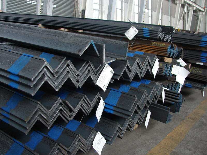
- Plates: For legs, nodes, decks. Common grades: S355G2/G3, S420G2/G3, S460G2/G3 (EN 10225), API 2W/2H Grades 50/60, ASTM A709 HPS. Thickness can exceed 100mm.
- Tubulars: For jacket braces and legs. Made from the above plates, formed and welded into pipes. They follow API 5L or structural pipe specifications.
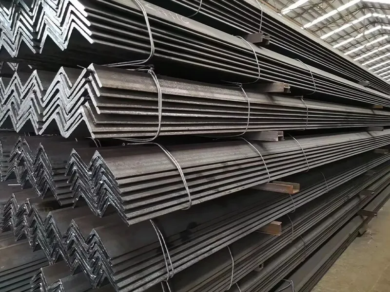
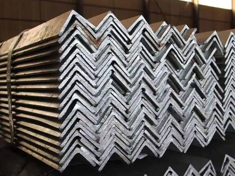
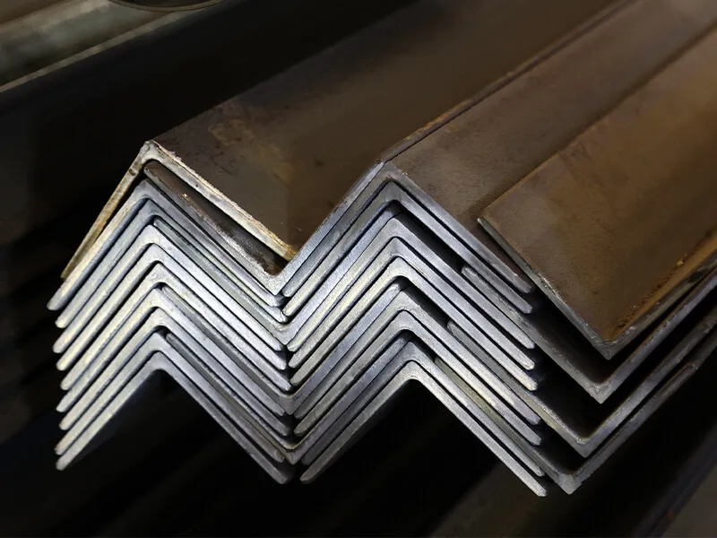
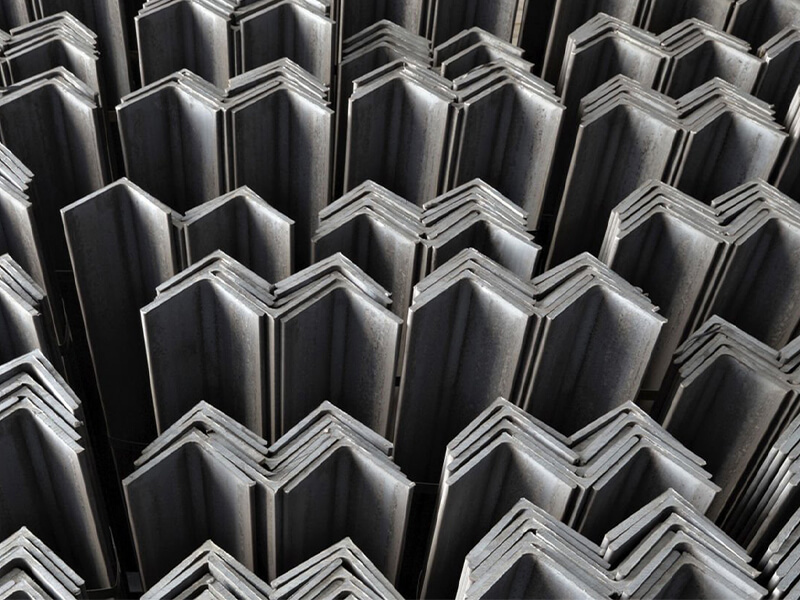
- Sections: Bulb Flat Steel is extensively used as stiffeners on plates for decks and hulls. Marine Angle Steel4 and L-shaped section steel are used for secondary framing, walkway supports, and brackets. Their consistent geometry and certified quality are crucial for easy fit-up during fast-paced fabrication.
2. Corrosion Protection System
Steel cannot fight the sea alone. It needs a multi-layer defense.
- Coatings: This is a science. Systems include:
- Shop Primer: A thin, weldable zinc silicate primer applied after blast cleaning.
- Intermediate/Finish Coats: High-build epoxy or polyurethane systems applied in the yard. They provide barrier protection.
- Splash Zone Protection: Extra thick coatings, rubber sheeting, or stainless steel cladding for the most aggressive area.
- Cathodic Protection (CP): For submerged parts. Sacrificial Anodes made of zinc or aluminum alloys are welded to the structure. They corrode instead of the steel. The anode material composition and weight are precisely calculated.
3. Fire and Blast Protection (For Oil & Gas)
Safety is paramount. In case of fire, the steel must not lose strength too quickly.
- Passive Fire Protection (PFP)5: Materials sprayed or boarded onto structural members. Cementitious materials6 (vermiculite-based) and intumescent paints7 (which expand when heated) are common. They insulate the steel, keeping it below critical temperature (typically 500°C) for a specified time (e.g., 60, 90, 120 minutes).
4. Secondary and Specialist Metals
- Stainless Steel: Grade 316/L is standard for seawater piping, handrails, ladders, and instrument housings in corrosive atmospheres.
- Fasteners: High-strength bolts (e.g., ASTM A325, A490 or equivalent) with hot-dip galvanizing or other corrosion protection. They must match or exceed the strength of the connected members.
- Cladding and Decking: Checkered plate (floor plate) for walkways, GRP (Glass Reinforced Plastic) for non-slip surfaces and lightweight walls.
5. The Critical "Material": Certification and Documentation
This is not a physical item, but it is the most important deliverable alongside the steel itself. The Material Traceability Dossier8 includes:
- Mill Test Certificates (MTCs) – Works Certificate 3.1 or 3.2
- Third-Party Inspection Reports (e.g., SGS, BV)
- Coating procedure and inspection reports
- Welding consumable certificates
- Bolt/nut certificates
Without this dossier, the platform cannot receive its final Class Certificate from DNV, ABS, etc. This is why our service includes organizing and providing clear, English SGS reports—it directly feeds into this critical project requirement that clients like Gulf Metal Solutions must fulfill for their end-users.
Conclusion
Designing with certified steel is a disciplined process from concept to installation. It integrates precise engineering methods, modular construction, and a system of complementary materials, all verified by traceable documentation.
-
Explore this link to understand the benefits and applications of HSLA steel in offshore construction. ↩ ↩ ↩ ↩ ↩
-
Learn about the crucial role of sacrificial anodes in preventing corrosion in marine environments. ↩ ↩ ↩ ↩ ↩
-
Explore the significance of high-strength bolts in maintaining the structural integrity of offshore platforms. ↩ ↩ ↩ ↩
-
Learn about the applications and benefits of Marine Angle Steel in the fabrication of offshore structures. ↩ ↩ ↩ ↩
-
Discover how PFP materials enhance safety and structural integrity in offshore oil and gas operations. ↩ ↩ ↩ ↩ ↩ ↩
-
Find out how cementitious materials contribute to fire safety in offshore environments. ↩ ↩ ↩
-
Discover how intumescent paints provide critical fire protection in offshore oil and gas facilities. ↩ ↩ ↩
-
Understand the importance of documentation in ensuring quality and compliance in offshore construction. ↩ ↩