You have perfect steel plates delivered to your shipyard. But after welding them together, the entire panel warps like a potato chip. This distortion ruins fit-up, delays the project, and costs a fortune to fix.
To ensure marine steel plate flatness before welding, you must verify incoming plate flatness against tolerance standards, prepare the surface correctly, use proper fixturing and welding sequences to control heat, and follow fundamental welding rules to minimize distortion.
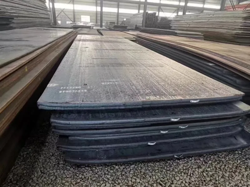
Last year, a shipyard in Thailand faced this exact problem. They were building a large deck section. The AH36 plates passed inspection on arrival. But after the welders finished the seams, the deck developed a severe 15mm bow. The whole section had to be cut apart and reworked. The problem started with their welding procedure and plate preparation. I see this often. Good steel is only half the battle. How you handle it before the first weld is just as critical. This guide will walk you through the steps to guarantee your plates stay flat from storage to finished weld.
What is the flatness tolerance for steel plates1?
You cannot demand a perfectly flat plate. But you can, and must, demand a plate that is flat enough. Knowing the official tolerance is your first line of defense against receiving substandard material.
The flatness tolerance for steel plates1 is defined by international standards like ASTM A62 or EN 100293. It specifies the maximum allowable deviation from a flat plane, often expressed as a measurement over a given span (e.g., 5mm in any 1m) or as a fraction of the plate’s length.
Understanding and Applying Flatness Tolerances
Tolerance is not a single number. It depends on the plate’s dimensions, the standard used, and the quality level you order.
Key Standards for Marine Plates
Two main standards govern flatness tolerances for the plates we supply:
-
ASTM A62 / A6M – Standard Specification for General Requirements for Rolled Structural Steel Bars, Plates, Shapes, and Sheet Piling. This is very common in the Americas and Asia.
- For plates, it provides a table for "Straightness of Plate Edges and Flatness." The tolerance depends on the plate’s width and thickness.
- Example: For a plate 8 feet (2440mm) wide or wider, the permissible deviation from a flat surface is 3/8 inch (9.5mm) when measured from a straightedge placed on the concave side. This is a common baseline.
-
EN 100293 – Specification for hot-rolled steel plates 3 mm thick or above – Tolerances on dimensions, shape and mass. This is the European standard.
- It defines different flatness classes4: Class A (Normal) and Class B (Higher).
- For Class A, the flatness tolerance is given as a maximum deviation in mm per meter of measured length. For plates over 4mm thick, a typical tolerance is 6mm per meter, but not more than a total maximum (e.g., 15mm for a 3m plate).
- Class B has tighter tolerances, usually half of Class A.
How to Check Tolerance on Site
You need a reliable method to check if a plate meets the spec.
- Tool: Use a precision straightedge5 (at least 1m long) and a set of feeler gauges.
- Method: Place the straightedge on the plate’s surface in several directions: along the length, across the width, and diagonally. Try to slide a feeler gauge underneath the straightedge at the point of maximum gap.
- Measurement: The thickness of the largest feeler gauge that fits is the local flatness deviation6 for that span. You compare this to the tolerance in your purchase order (e.g., "Flatness to ASTM A62" or "Max 4mm in any 1m span").
Why This Matters Before Welding
A plate that is already near or beyond its flatness tolerance is a problem.
- It will be harder to fit up with adjacent plates, creating large gaps that require excessive welding.
- Excessive welding to fill gaps introduces more heat, which causes more distortion.
- Trying to force a warped plate into position with clamps puts stress into the structure before welding even begins.
Here is a simple reference table for common expectations:
| Plate Thickness | Typical Application | Reasonable Flatness Expectation (Pre-welding) | Action if Exceeded |
|---|---|---|---|
| 10-20 mm | Hull plating, decks | ≤ 5 mm over any 2m span | Acceptable for most work. Can be pulled flat during fit-up. |
| 20-40 mm | Keel plates, critical members | ≤ 3 mm over any 1m span | Check carefully. May require leveling if severe. |
| > 40 mm | Rudder stocks, foundations | ≤ 2 mm over any 1m span | Tighter tolerance needed. Discuss with supplier on inspection. |
My advice: Always specify the flatness standard in your purchase order. For critical applications, you can specify a tighter-than-standard tolerance, but expect a higher cost. When our clients like Gulf Metal Solutions order plates, they often specify "ASTM A62 flatness" as a minimum. For some projects, they request a pre-delivery inspection report7 with flatness measurements. This ensures the plates start the welding process on the right foot.
How to keep a plate from warping when welding?
Welding creates intense localized heat. The metal expands where it’s hot and contracts as it cools. This uneven heating and cooling is the sole cause of welding distortion. Your job is to manage this force.
You keep a plate from warping when welding by controlling heat input, using a planned welding sequence, employing strong backstep or skip welding techniques, and properly fixturing or clamping the plate to a rigid base to resist movement during the process.
A Strategic Battle Against Heat
You cannot stop the heat, but you can control its effects. Think of it as a battle plan.
Technique 1: Control Heat Input1
More heat means more expansion and more shrinkage. You must use the minimum heat needed to make a good weld.
- Use the correct amperage and voltage. Do not overweld. Follow the Welding Procedure Specification (WPS)2.
- Choose the right process. For thin plates, processes like Metal Inert Gas (MIG) or Tungsten Inert Gas (TIG) with lower heat input are better than high-heat processes like Stick welding.
- Increase travel speed if possible. A faster weld puts less total heat into the plate.
Technique 2: Use a Smart Welding Sequence3
Do not weld from one end to the other in a continuous bead. This concentrates shrinkage in one direction, pulling the plate into a bow.
- Backstep Welding4: Weld short segments in the direction opposite to the overall progress. For example, if the final weld is from left to right, you weld a small segment at the far right end first, then one next to it moving leftward. This localizes shrinkage.
- Skip (Stagger) Welding5: For long seams, weld a short section in the middle, then one at the far left, then one at the far right, alternating. This balances the pulling forces.
- Balance the weld: On a double-sided weld, weld one side, then immediately weld the opposite side. The second weld’s shrinkage can counterbalance the first.
Technique 3: Use Mechanical Restraint (Fixturing)6
This is physical prevention. You hold the plate so it cannot move.
- Strongback Bars: Weld or clamp heavy steel bars (strongbacks) across the seam on the opposite side of the weld. These bars absorb the shrinkage force. They are removed after welding.
- Clamps and Dogs: Use plenty of clamps to hold the plate firmly to the fabrication bed or a stiff backing plate.
- Pre-setting (Pre-bowing): If you know the weld will cause an upward bow, you can preset the plate by bending it slightly downward before welding. The weld shrinkage will then pull it flat.
Technique 4: Peening (Use with Caution)7
Peening involves lightly hammering the weld bead while it is still hot. This stretches the metal and can counteract some shrinkage. Warning: This must be done carefully on marine steels to avoid cracking and must be approved by the welding procedure.
The strategy is to combine these methods. Here is a practical action plan for a long butt weld:
| Step | Action | Purpose |
|---|---|---|
| 1. Preparation | Clamp plates firmly to a flat, heavy welding bed. Use alignment dogs to ensure flush edges. | Prevent movement at the start. |
| 2. Tack Welding8 | Place small tack welds every 300mm along the seam. | Hold alignment without much heat. |
| 3. Welding Sequence | Use backstep and skip welding. Break the 2m seam into 200mm segments. Weld segment 6, then 1, then 5, then 2, etc. | Distribute heat and shrinkage evenly. |
| 4. Heat Control | Use the WPS-recommended settings. Let the plate cool between segments if needed. | Minimize overall thermal expansion. |
| 5. Inspection | Check flatness after each major section. | Catch distortion early for correction. |
Remember, some distortion is always expected. The goal is to control it within acceptable limits so that the final structure meets the dimensional tolerances of the ship design.
How to prepare the surface before welding?
A perfect weld cannot be made on a dirty or poorly prepared surface. Surface preparation1 is like priming a wall before painting; it ensures a strong, clean bond and prevents defects.
To prepare the surface before welding, you must remove all contaminants like mill scale, rust, oil, paint, and moisture from the welding zone. This is typically done by grinding or machining to create a clean, bright metal bevel, followed by cleaning with a solvent.
The Critical Steps for a Clean Weld Zone
Surface preparation1 has two main goals: 1) Ensure weld quality, and 2) Minimize distortion-causing impurities.
Step 1: Removal of Coatings and Contaminants
Anything that is not base metal can cause weld defects.
- Mill Scale: The dark oxide layer on hot-rolled steel (like AH36 plates) must be removed. Mill scale2 can cause porosity (gas pockets) in the weld. It also has a different thermal expansion rate than steel, which can contribute to uneven stresses.
- Rust: Rust contains moisture (H2O). Under the welding arc’s heat, this moisture breaks down into hydrogen and oxygen. Hydrogen can dissolve into the molten weld metal and cause hydrogen-induced cracking (HIC) or cold cracking, especially in thicker plates. This is a serious, delayed failure.
- Oil, Grease, Paint, Dirt: These introduce carbon and other impurities. They cause porosity, lack of fusion, and brittle welds.
Method: Use a grinding wheel, needle gun, or sandblasting to clean a strip at least 25mm (1 inch) on each side of the intended weld seam. The metal should be bright and shiny.
Step 2: Edge Preparation (Bevelling)
For plates thicker than about 6mm, you usually need to create a groove (bevel) to ensure the weld penetrates fully to the root.
- Why bevel? The welding arc cannot penetrate thick metal in a single pass from the top. A bevel provides a pathway for the weld metal to fill the entire joint.
- Common Joint Types:
- Single-V Groove: One side is beveled. Used for plates you can only access from one side.
- Double-V Groove: Both sides are beveled. This is preferred for thicker plates as it balances the welding from both sides, reducing distortion.
- Bevel Angle & Root Face: The standard bevel angle is 30-37.5 degrees per side. A small flat land called the "root face" (1-2mm) is left at the bottom to prevent burn-through.
Step 3: Final Cleaning
After grinding or machining, tiny particles and grinding dust remain.
- Use a wire brush (stainless steel brush for stainless steel) to remove loose particles.
- Wipe the area with a lint-free cloth and a recommended solvent (like acetone) to remove any remaining oils or moisture from handling.
- Crucial Point: Do not use chlorinated solvents near stainless steel, as they can cause corrosion.
How Good Preparation Affects Flatness
Poor preparation indirectly causes distortion:
- Contaminants cause poor weld quality. A porous or defective weld may need to be gouged out and re-welded. This double heating distorts the plate more.
- Inconsistent bevels lead to uneven weld volume. One side may require more weld metal than the other, creating unbalanced shrinkage forces that pull the plate out of shape.
- Moisture from rust increases hydrogen levels. To prevent cracking, you may need to use pre-heat. Incorrect pre-heat can also affect distortion.
A proper, clean, and consistent edge preparation allows for a smooth, controlled welding process with predictable shrinkage. This is the foundation for maintaining flatness.
What is the golden rule in welding?
If you ask ten experienced welders, you might get ten different tips. But there is one fundamental principle that underpins all successful welding, especially for critical structures like ships. It is the rule that prevents the most failures.
The golden rule in welding is to always maintain a stable, consistent arc length1. This simple rule controls heat input2, penetration, bead shape, and defect formation, making it the foundation for creating a strong, sound weld every single time.
Why Arc Length is Everything
The arc is the heart of the welding process. It is the electric "flame" that melts the metal. The distance between the welding electrode3 (or wire) and the workpiece is the arc length. Controlling this distance is the welder’s primary skill.
The Physics of the Arc
The arc is a column of superheated, ionized gas that conducts electricity. Its characteristics change with length:
- Short Arc: The electrode is close to the workpiece.
- Heat Input: Higher, more concentrated. Better penetration.
- Voltage: Lower.
- Risk: The electrode can dip into the weld pool (short-circuit), causing spatter and sticking.
- Long Arc: The electrode is far from the workpiece.
- Heat Input: Lower, more spread out. Less penetration.
- Voltage: Higher.
- Risk: The arc becomes unstable, can wander, and causes excessive spatter, undercut, and porosity. Shielding gas coverage is also less effective.
Consequences of Ignoring the Golden Rule
An inconsistent arc length leads directly to weld defects4 that compromise strength and can cause distortion:
- Lack of Penetration: A long arc does not transfer enough heat to melt the base metal deeply. The weld sits on top of the joint like a caterpillar, with no strength inside. This is a critical defect.
- Undercut: A long, fast arc can melt the edges of the groove but not fill them, creating a sharp notch. This notch is a perfect stress concentrator and can become a crack initiation point.
- Porosity: A long arc allows air to get into the shielding gas envelope. Nitrogen and oxygen contaminate the weld pool, creating tiny gas pockets (porosity) that weaken the weld.
- Excessive Spatter: An erratic arc blows molten metal droplets everywhere, wasting material and creating a mess to clean up.
- Inconsistent Bead and Heat Input: This is key for flatness. If one part of the weld is made with a short arc (high heat) and another with a long arc (low heat), the shrinkage will be uneven. This uneven pulling force is a direct cause of warping and distortion.
How to Apply the Rule in Practice
For a welder, maintaining arc length means constant, focused attention. It is a manual skill.
- In Stick (SMAW) Welding: You must feed the electrode downward at the exact rate it is melting to keep a distance of about the electrode’s diameter.
- In MIG/MAG (GMAW) Welding: The contact tip-to-work distance5 (CTWD) is critical. The welder must maintain a consistent gun angle and distance, often guided by the sound of a steady "crackling" arc.
- In TIG (GTAW) Welding6: The arc length is often set precisely, and the welder uses a rest or steady hand to keep the tungsten electrode at a fixed distance from the work.
This rule connects everything: Proper surface preparation gives you a clean area to see and control the arc. Controlling the arc (and thus heat input2) is the main technique to prevent warping. Following a welding sequence manages the effects of that controlled heat. It all starts with a stable arc. When we audit our mill partners’ welding procedures for certified products, the consistency of the welder’s technique—fundamentally, their arc control—is always a key point of inspection.
Conclusion
Ensuring plate flatness is a process that starts with inspection, depends on meticulous preparation, and is secured through controlled welding techniques. Master these steps, and you master distortion control.
-
Understanding this principle is crucial for achieving strong, defect-free welds, making it a must-read for welders. ↩ ↩ ↩ ↩ ↩ ↩
-
This resource will clarify how heat input influences weld quality and integrity, essential for any welder. ↩ ↩ ↩ ↩ ↩ ↩ ↩ ↩
-
Exploring this topic will enhance your knowledge of electrode selection and its impact on welding performance. ↩ ↩ ↩ ↩
-
Learning about these defects can help you avoid costly mistakes and improve your welding skills. ↩ ↩ ↩
-
This information is vital for MIG/MAG welders to ensure optimal performance and weld quality. ↩ ↩ ↩
-
This guide will provide essential techniques for TIG welders to achieve precision and consistency. ↩ ↩ ↩
-
Peening can counteract shrinkage but must be used carefully; understanding its application is key to successful welding. ↩ ↩
-
Tack welding is essential for maintaining alignment and preventing movement, ensuring a successful welding process. ↩