
Underestimating steel quantities from drawings causes emergency orders, price spikes, and slipways that stand still. I have watched it happen. This guide shows you how I turn a drawing into a defensible order.
To estimate marine angle steel quantities from shipbuilding drawings, list every angle member by frame number and section size, convert each line to length in metres using the frame or stiffener spacing, multiply by the kg/m value from a standard section table, add a cutting and waste allowance of roughly 3–7%, then round up to full mill lengths of 6, 9, or 12 metres.
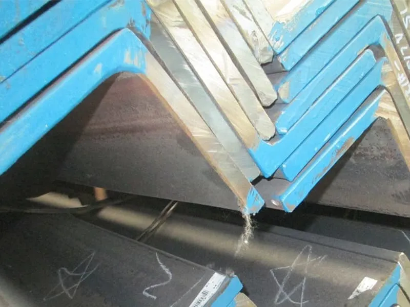
Most buyers I talk to can read a quotation fine, but they freeze when a naval architect sends them a midship section and a shell expansion drawing with no material list attached. That is normal. Drawings speak in ribs, frames, and bracket numbers, not in purchase orders. The bridge between the two is a method, and the method is learnable in an afternoon. I run this same method in my head every time a client from Vietnam or Pakistan asks me to price “the angles for one barge” off a PDF. In this article I walk you through the three steps I use: what to read on the drawing, how to convert dimensions into weight, and which allowances keep the estimate honest when the steel actually arrives.
What Should You Read First on a Shipbuilding Drawing Before Counting Angles?
Open the midship section drawing and the first thing you feel is panic. Lines everywhere. If you start counting from the wrong place, your whole takeoff collapses by the second page.
Start with the midship section drawing to identify the standard frame profile sizes, then use the shell expansion and construction profile drawings to count each member by frame number. The midship section tells you the typical angle size; the frame spacing on the construction drawing tells you how many pieces each run needs.
The Three Drawings That Matter
I never work from a single drawing. A complete takeoff for marine angle steel needs three sheets, and they do different jobs.
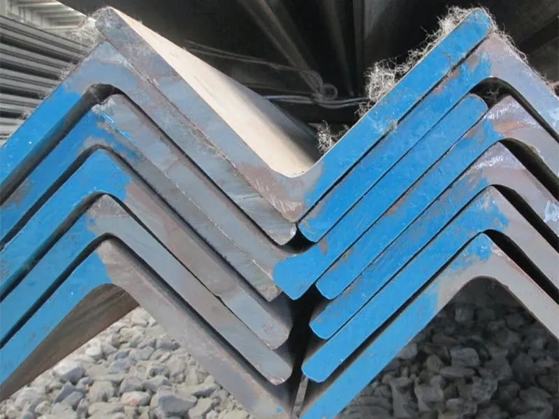
The midship section drawing shows the typical structural arrangement at the strongest part of the hull. It tells you the standard sizes: which frame members are L100x100x8, which stiffeners are L75x50x6, where the deck beams change size. Shipyards design with a small set of repeated sections, and the midship section is where those repeats are declared.
The shell expansion drawing shows the hull “unwrapped” flat. Every longitudinal stiffener, every strake boundary, every transverse frame position appears here as a line. When I count angle runs on the shell side of a cargo barge, this is my sheet.
The construction profile or frame drawing shows each frame position along the ship’s length, usually numbered from the after perpendicular. The frame spacing matters more than anything else in your calculation. Many small and mid-size cargo vessels use frame spacing somewhere between half a metre and one metre, but the exact value is always printed on the drawing or stated in the class-approved structural plan. Never assume it. Read it.
Here is the checklist I tick before I write a single number into my estimate sheet:
| Drawing Item | What It Tells You | What Goes Wrong If You Skip It |
|---|---|---|
| Frame spacing | Length of each transverse angle member | Piece count wrong by 20% or more |
| Section table / legend | Official size designations (L100x100x8, etc.) | You guess sizes and the quote mismatches the design |
| Grade callouts | Which members need AH36 instead of Grade A | Mixed grades in one bundle, certification trouble |
| Snipe and bracket details | End cuts that reduce usable length | Offcut losses higher than planned |
| Scantling notes | Class rule references (ABS, LR, BV, DNV) | Wrong certified material offered by the mill |
One habit from my side of the fence: I always check whether the drawing gives member lengths directly or makes me derive them from spacing. Repair and conversion drawings often list “frame #45, L150x90x10, 2.4 m” right on the sheet. New-build structural drawings usually do not. New-builds make you multiply. The difference decides whether your estimate takes one hour or one day.
Why the Drawing Lies a Little (and How to Compensate)
Drawings show the finished structure, not the material you must buy. A frame member shown as 6 metres long on the drawing will be cut from a 6 metre bar, but the cut loses 3–5 mm to the saw, the ends may need sniping for bracket clearance, and if the member lands in a curved shell area, it may need extra length for bending trial and error. I once quoted angles for a deckhouse refit where the yard assumed zero cutting loss and came back to me two weeks later needing eleven extra bars of L63x63x6. Not a disaster, but an annoying air-freight-free delay they did not budget for. The lesson stuck: read the drawing for geometry, then add allowances in a separate, visible line of your estimate. Never hide them inside a rounded number.
How Do You Turn Steel Angle Dimensions Into Weight and Length Numbers?
This is the step buyers fear, so they copy numbers from old orders. That works until the new design uses a different section. Then the estimate is wrong in a way nobody notices until the container is unloaded.
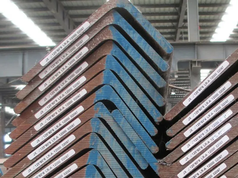
Convert each angle member to weight with the formula kg = t x (A + B − t) x 0.00785 x L, where A and B are the leg widths in mm, t is the thickness in mm, and L is the length in metres. For final orders, always replace this theoretical value with the kg/m figure from a standard section table, because rolled corner radii make the real bar slightly heavier.
The Geometry, in Plain Language
An angle is just two rectangles joined at a corner, and the corner is counted twice if you are careless. The honest cross-sectional area of an unequal angle is:
Area (mm²) = t x (A + B − t)
Multiply that area by the length in metres and by the steel constant 0.00785 (which is the density of steel, 7.85 g/cm³, rearranged into convenient units), and you get kilograms. The repair-estimating world uses the same logic with a simpler habit: many estimators round steel’s specific gravity up from 7.84 to 8 to speed the mental math, which inflates the result by about 2%. Fine for a repair budget, not fine for a purchase order where you pay by the tonne.
Let me work one example the way I do it at my desk. The drawing calls for 40 transverse frames of unequal angle L150x90x10, frame spacing gives 12 metres of run per “frame set” after allowing for the curved shell connection… actually, let me keep it cleaner: the drawing lists each frame at 12 metres of total angle run. Per frame:
- Area = 10 x (150 + 90 − 10) = 2,300 mm²
- Weight = 2,300 x 12 x 0.00785 = 216.7 kg per frame
- For 40 frames: 216.7 x 40 = 8,668 kg, or about 8.7 tonnes
That is the theoretical weight. Now compare it against the table value. Published section tables for hot-rolled equal angles list L100x100x10 at 15.12 kg/m, while the sharp-corner formula gives 14.92 kg/m. The table is about 1.3% heavier because the rolled root radius and toe geometry add real material that the simplified formula ignores. Small per bar, but on an 8.7-tonne order that 1.3% is over 100 kg, and the mill will happily charge you for every gram that crosses the weighbridge.
| Method | L50x50x5 | L100x100x6 | L150x90x10 |
|---|---|---|---|
| Formula kg/m (t x (A+B−t) x 0.00785) | 3.73 | 9.19 | 18.05 |
| Typical published table kg/m | 3.77 | 9.37 | ≈18.0 |
| Difference | +1.1% | +1.9% | −0.3% (unequal angle, table varies) |
The pattern is simple. The formula is your sanity check. The table is your number. When I build a quotation for a client, the price line always uses the table value and the certificate weight, and I show the formula value in a notes column so the buyer can audit me. Transparency here has saved me more arguments than any discount ever has.
From Weight Back to Pieces and Mill Lengths
Mills do not sell “kilograms”. They sell bars in standard lengths, typically 6, 9, and 12 metres for marine angles. So the last step of every takeoff runs backwards: total weight to total length to piece count.
Say your estimate needs 1,120 metres of L100x100x8. In 12 metre bars, that is 93.3 bars, so you order 94. The leftover 0.7 bar is your first offcut. Now stack the cutting plan: if individual members are 2.4 metres, five members fit exactly into one 12 metre bar and offcuts approach zero. If members are 2.5 metres, four fit per bar and you throw away 2 metres each time, a 16.7% waste on that size. Same drawing, same weight, but two very different purchase quantities. This is why I ask fabricators for their cutting list, not just their weight summary, whenever the order is big enough to matter. For more on how cutting plans affect what you actually pay, see how to plan angle lengths to minimize offcuts and how to estimate cutting losses when purchasing marine angle steel.
Which Allowances and Checks Keep Your Marine Angle Estimate Realistic?
Even a perfect formula gives a wrong order if the allowances are guessed. Buyers who skip this step either pay for steel they never use or scramble for an emergency top-up order at spot prices.
Add a visible waste allowance of roughly 3–7% for cutting loss, sniping, and handling damage, verify the estimate against the certificate weight after delivery, and reconcile every variance. The allowance is not padding, it is the documented cost of turning mill bars into finished members.

Building the Allowance, Line by Line
I split allowances into three named lines, because lumping them into one “wastage” number is how estimates drift.
Cutting loss comes from the saw or torch kerf and the unusable short ends. If members are short relative to bar length, this line grows fast, as the 2.5 metre example above showed. It can be near zero with a good nesting plan or above 10% with a bad one.
Fit-up and handling loss covers bars damaged in transport or mis-cut during fabrication. For well-run yards this is small, 1–2%. For yards stacking bars with forklifts on muddy ground, I have seen it double. Look at your own yard honestly.
Design revision margin is the controversial one. Drawing revisions happen. A late revision that thickens two frame groups from L100x100x8 to L100x100x10 turns into a new order for a different section, and the old bars become slow-moving stock. I keep this line at zero in the purchase order but flag it in my cover email, so the client consciously decides the risk instead of me. My rule after a decade in export sales: never hide a risk the buyer could have priced cheaper than you.
Before I close this section, one port-side truth I tell every new client: the weight on the mill test certificate, the weight on the packing list, and the weight on your invoice will be three numbers that are close but not identical, and each one is correct for its own purpose. The certificate weighs the product per the standard’s tolerance rules. The packing list weighs the shipment as bundled. The invoice usually follows the certificate. If your takeoff ignores the roughly 1–2% spread between theoretical and actual, your receiving team will report a “shortage” that never existed, and everyone wastes a week on emails. I have sat through that meeting. It is boring and expensive.
| Allowance Line | Typical Range | Main Driver | Where It Belongs |
|---|---|---|---|
| Cutting loss | 0–10% | Member length vs mill bar length | Purchase quantity |
| Fit-up / handling | 1–2% | Yard material handling discipline | Purchase quantity |
| Design revision margin | 0% (flagged) | Drawing revision probability | Cover note, not order |
| Theoretical-to-actual gap | 1–2% | Rolled radii and tolerance | Weight reconciliation sheet |
The Final Reconciliation Loop
The estimate is not finished when the order ships. It is finished when the last bar is issued to fabrication and you compare three totals: ordered, received, and consumed. My clients at Gulf Metal Solutions in Saudi Arabia run this loop on every marine angle order, and it is one reason their quantity disputes are rare. They check the packing list against the order before the vessel departs, verify bundles at Dammam port against the same sheet, and file any variance while the evidence is still on the quay. When a mismatch does appear, having the original takeoff sheet with the table kg/m values, the allowance lines, and the piece counts turns a hostile argument into a ten-minute arithmetic review. That is the quiet payoff of doing the estimate properly: not just a better order, but a paper trail that ends disputes before they start.
Conclusion
Read three drawings, convert with the formula but price with the table, and carry your allowances in visible lines. Do that, and your marine angle estimate survives contact with the weighbridge.