
A marine angle bar takes intense heat on one thin leg, and the frame moves. The leg rotates, the panel bows, and straightening costs follow.
Excessive distortion when welding marine angle steel comes from four causes: too much weld metal for the joint, one-sided heat with no balancing weld, poor fit-up that lets the bar move while it cools, and a sequence that concentrates heat in one zone instead of spreading it along the frame.
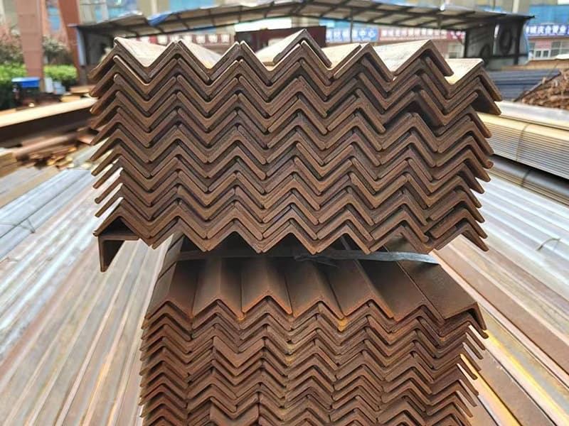
Most buyers I deal with do not ask about distortion when they place the order. They ask about grade, length tolerance, and price per tonne. Then three weeks later I get the photo: a stiffener that has pulled a 6 mm plate into a visible wave, or an angle bar whose upstanding leg has tilted 4 mm over a 12 m run. That photo is always more expensive than the steel. In this article I want to walk through what actually drives the movement, because once you see the four causes clearly, the fix is usually a change in the weld procedure rather than a change in the material.
Why Does a Single Fillet Weld Rotate the Leg of a Marine Angle Bar?
Weld shrinks as it cools, and it shrinks hard. One fillet on one leg pulls that leg toward the plate, and nothing on the other side pulls back.
A single fillet weld rotates the leg because the weld metal contracts about 10 percent in volume as it solidifies, and that contraction sits entirely on one side of the angle’s neutral axis. The leg hinges around the root and the bar bows along its length.
The Shrinkage That Nobody Can Weld Out
Carbon steel expands roughly 12 microstrain for every degree Celsius it gains. That sounds small until you put it into a real joint. A fillet weld pool reaches well above 1,500 degrees Celsius, and the metal around it stays at ambient temperature. The hot zone wants to grow, the cold zone refuses to let it, so the hot metal yields in compression. Then it cools. Now the same zone wants to shrink, and this time the cold metal holds it in tension.
That is the engine of every distortion problem. The weld does not just sit there. It arrives hot, gets squeezed while hot, and then pulls while cold. The pull is what you see afterwards.
A welder cannot avoid this cycle. But he can control how much metal goes through it, and where that metal sits relative to the rest of the section. Those two levers decide most of the outcome.
Why an Angle Bar Is Worse Than a Flat Bar
An angle has an asymmetric stiffness. The two legs meet at a corner, and the shear centre sits outside the section, not inside it. When you run a fillet along one toe, the contraction force acts at a distance from that shear centre. The result is not just bending. It is bending plus twist.
I have watched this on a block in a yard in [Zora will replace]. The welders ran a continuous 8 mm fillet along the heel of a 150×150×12 angle, one pass, root to end, no backstep. The bar came out with a visible helix. The straight edge showed contact at one end and a 9 mm gap at the other. Nobody had changed the grade or the fit-up. They had simply put all the heat in one line, in one direction, on one side of an asymmetric section.
A flat bar under the same procedure bows. An angle bar bows and twists, and twist is much harder to straighten afterwards.
The Weld Size You Actually Need
Most excessive distortion I see is not a welding skill problem. It is a weld size problem. The drawing says “fillet 6 mm” and somebody runs 9 mm “to be safe”. Weld metal cross-section grows with the square of the leg, so that decision is not a 50 percent increase in deposited metal. It is more than double.
| Fillet leg (mm) | Theoretical throat (mm) | Cross-section (mm²) | Relative weld metal |
|---|---|---|---|
| 5 | 3.5 | 12.5 | 1.00 |
| 6 | 4.2 | 18.0 | 1.44 |
| 8 | 5.7 | 32.0 | 2.56 |
| 10 | 7.1 | 50.0 | 4.00 |
Going from a 6 mm to an 8 mm leg adds 78 percent more metal, and that extra metal adds 78 percent more contraction force to the same joint. The joint does not get meaningfully stronger in most hull details, because the design was already governed by the connected plate, not by the weld. What it does get is more movement.
This is where a procurement person can help without touching a torch. When you review a fabrication specification, ask whether the fillet sizes are minimum required by the rule or “standard practice”. On many stiffener connections, intermittent welding is permitted, and it can cut deposited metal by up to 75 percent compared with a continuous run. That single change removes most of the heat that causes the problem.
Which Fit-Up and Handling Mistakes Multiply the Movement?
A wide gap is a reservoir for weld metal, and a bar that was already bent has nowhere to go but further out of shape.
Wide, uneven root gaps force extra weld metal into the joint and shrink unevenly along its length. Bars stored or lifted without support arrive bowed, and forcing them into position locks that bow into the frame as residual stress.
Gap, Groove, and the Hidden Extra Metal
Fit-up is the cheapest place to control distortion, and the easiest place to lose control. A 2 mm gap that runs the full length of a joint is a different structure from a 2 mm gap at one end and a tight butt at the other.
The rule our fabrication customers work to is simple. Thin material gets 1 to 2 mm. Medium and heavy sections get 2 to 3 mm. The gap must be consistent, because consistent gap means consistent shrinkage. Uneven gap means the weld pulls harder at one end, and the bar curves toward that end.
When the gap runs over, the correct response is to dress or re-cut the edge. The wrong response is to fill it with weld metal or pull it shut with a come-along. Both approaches convert a fit-up error into locked stress, and locked stress comes back as movement the moment the clamps come off.
Tack welds belong in the same conversation. They are not a formality. Short, sparse tacks let the joint open as the weld heats it. I like tacks every 300 mm on a long stiffener, 20 to 30 mm long on thinner sections and 30 to 50 mm on heavier ones, with sound throats. A cracked or hollow tack is worse than no tack, because it fails exactly when the heat arrives.
Handling Damage That Gets Welded In
Angle bars are long, flexible, and easy to bend in a sling. A 12 m bar picked at a single point will sag under its own weight, and if it is stacked on uneven dunnage in the yard, it will take a set.
The Chinese yard practice I have seen is strict about this, and I think it is right. Profiles are straightened before pre-assembly, and any bar that is twisted or bowed is corrected or rejected before it reaches the fitter. Deformation is not allowed to travel into the next process. If you weld a bowed bar onto a flat plate and pull it straight with clamps, you are not removing the bow. You are storing it as residual stress, and it will release later, usually after the block is painted.
There is also a storage point that buyers rarely consider. Angle bars stacked in a yard for months without support develop a permanent set from their own weight, especially the smaller sections. If your supplier ships 6 m bars loose in a container with no dunnage, some of them will arrive curved. That curve is not a mill defect. It is a packing decision, and it becomes a fabrication problem three weeks later.
| Fit-up or handling fault | What it does to the weld | How it shows up later |
|---|---|---|
| Gap over 3 mm and uneven | Extra weld metal, uneven shrinkage | Bar bows toward the wide end |
| Sparse or cracked tacks | Joint opens during welding | Leg rotation and root gap growth |
| Bar bowed before fitting | Clamps force it flat | Spring-back after unclamping |
| Single-point lifting of 12 m bars | Permanent set from self-weight | Straightness fails at fit-up |
| No straightening before assembly | Deformation carried forward | Cumulative panel wave |
How Do You Control Distortion Without Locking Stress Into the Frame?
You balance the heat, restrain it gently, and correct the shape before the weld is finished, not after the block is painted.
Control comes from balanced double-sided fillets where the detail allows, backstep and skip sequences that spread heat, pre-setting the bar against the expected movement, and restraint that holds alignment without turning the joint into a rigid crack risk.
Balance Before You Restrain
The first choice is geometric. If a connection can carry a fillet on both sides of the leg, two balanced welds largely cancel each other’s angular pull. If it cannot, the next best option is to alternate sides along the length so the net moment stays near zero.
Restraint is the second choice, and it is the one that gets overused. Strongbacks and fixtures hold the part in place while it cools, but they do not reduce the shrinkage. They just stop it from showing until release. A heavily restrained joint stores more residual stress, and in higher-strength hull grades such as AH32 and AH36 that raises the cold-cracking risk, particularly on thick sections and in low ambient temperature.
So the order matters. Reduce weld volume first. Balance the heat second. Restrain third, and only as much as alignment actually requires. A yard that clamps harder to fix a distortion problem is usually making the next problem.
Sequence, Direction, and the Backstep Habit
Sequence is free. It costs nothing but discipline, and it is where most of the easy wins sit.
Start from the middle of the joint and work outward, so the bar is free to move at both ends instead of being trapped at one. Weld short segments and let each one cool before the next. On a 1 m joint, 100 mm backstep segments are a good starting point: weld a segment, step back, weld the next one against the direction of overall travel. The heat never accumulates in one place long enough to pull the section.
Symmetry matters just as much at panel level. On a stiffened panel, weld the stiffeners in a staggered order from the centre line outward, alternating port and starboard, rather than finishing one side of the panel before starting the other. The panel then shrinks toward its own centre instead of curling to one side.
For heavier sections, preheat helps in a different way. Above roughly 15 mm, bringing both the bar and the plate to about 100 degrees Celsius slows the cooling rate and lowers the risk of hydrogen cracking. It does not remove distortion, but it makes the weld less brittle while the shrinkage happens. A low-hydrogen electrode suits these joints.
Pre-Setting, Shrinkage Allowance, and the Correction You Want to Avoid
Two more tools are worth knowing. Pre-setting means building the assembly slightly out of true in the opposite direction, so that weld shrinkage pulls it back to flat. It works well on repeated details, because the amount of movement is repeatable once the procedure is fixed. It works badly on one-off details where nobody measured the movement first.
Shrinkage allowance is the other half. Pre-setting handles rotation and bowing. Allowance handles the fact that the whole assembly gets shorter. Long stiffened panels lose length and width, and if the cutting list ignores that, the block comes up short at the erection stage.
Correction is the last resort, and it has a cost that seldom appears in the tender. Flame straightening adds another heat cycle, consumes gas and labour, and can leave its own residual pattern if it is done by feel. I have seen a block go through straightening twice and still fail the flatness check, because the first correction was applied while the panel was still restrained.
| Control measure | What it fixes | What it costs | Risk if skipped |
|---|---|---|---|
| Minimum fillet size per drawing | Angular rotation, bowing | Nothing, if specified correctly | 50 to 100 percent extra weld metal |
| Intermittent or skip welding where permitted | Heat input along the joint | Slightly more planning | Continuous heat, panel wave |
| Balanced double-sided fillets | Leg rotation | One extra pass | Twist and angular distortion |
| Backstep, centre-out sequence | Heat concentration | Welder discipline | Bowing toward the finish end |
| Pre-setting the detail | Repeatable angular movement | Measuring the first piece | Straightening after painting |
| Shrinkage allowance in the cutting list | Overall length and width loss | A few mm of stock | Short blocks at erection |
| Light restraint with strongbacks | Alignment during cooling | Setup time | Higher residual stress and cracking |
The comparison that matters most for a buyer is not between two welding techniques. It is between controlling distortion at the drawing stage and paying for it at the straightening stage. The first costs a conversation. The second costs a shift.
One more point from my side of the business. Distortion complaints often arrive as quality complaints about the steel, and they are almost never about the steel. A mill certificate, a leg tolerance of plus or minus 1.5 mm, and a length tolerance of 0 to 50 mm will not cause a 9 mm wave in a panel. Heat and sequence cause that. When a customer sends me a photo of a warped frame, I ask three questions: what fillet size, what sequence, and how was it clamped. The answers usually explain the photo before anybody opens the MTC.
We supply angle bars to fabricators in Saudi Arabia, Vietnam, and Malaysia, and the ones who get clean results tend to do the same things. They straighten before fitting. They keep the gap consistent. They run the smallest fillet the rule allows. And they weld from the middle out. None of that is exotic. It is just discipline, applied before the heat arrives.
Conclusion
Distortion in welded marine angle steel is heat, volume, and sequence, not bad steel. Cut weld metal early, balance the passes, and fix fit-up first.