
You see a ship’s skeleton. Angles run everywhere. Without them, the hull would buckle.
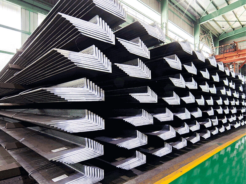
Marine L‑shaped steel is used as longitudinal and transverse stiffeners, frame reinforcements, and bracket components in ship hulls. It strengthens the bottom, side shell, and deck, and connects to plates and bulb flats through fillet welds and end connections.
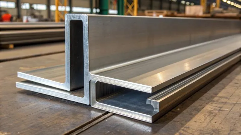
I have supplied L‑shaped steel to shipyards for years. When I walk through a hull under construction, I see the same patterns – L‑sections everywhere. They are not random. Their placement follows clear engineering rules. Let me walk you through where and how L‑shaped steel is used in modern ship hulls.
Where Are L‑Shaped Sections Installed as Longitudinal and Transverse Stiffeners in the Hull?
A hull without stiffeners is like a paper box without creases. It cannot hold its shape.
L‑shaped sections are installed as longitudinal stiffeners running fore‑aft along the bottom, side, and deck. They are also used as transverse frames (floor frames, web frames) that run port‑starboard. Longitudinals resist bending from waves. Transverse frames maintain the cross‑section shape.
Diagram showing longitudinal and transverse L-section stiffeners in ship hull
The grid that gives a ship its strength
I remember a naval architect explaining it to me: "Think of the hull as a grid. The plates are the skin. The L‑sections are the bones." So let me break down the two directions.
First, longitudinal stiffeners (running front to back). These are attached to the inner bottom, side shell, and underside of the deck. Their job is to distribute the bending stress caused by waves.
| Location | Typical L‑Section Size | Spacing (center to center) | Function |
|---|---|---|---|
| Inner bottom | L125x125x12 to L150x150x15 | 600‑900mm | Support cargo loads, resist bottom bending |
| Side shell | L100x100x10 to L125x125x12 | 700‑900mm | Prevent side shell buckling |
| Deck underside | L100x100x10 to L150x150x15 | 700‑1000mm | Stop deck plating from deflecting under wave slamming |
Second, transverse frames (running side to side). These are vertical or near‑vertical members that resist crushing forces and maintain the hull’s cross‑section shape.
| Frame Type | L‑Section Size | Spacing | Role |
|---|---|---|---|
| Floor frames (bottom) | L150x150x15 to L200x200x20 | 2.5‑3.5m | Support bottom longitudinals |
| Side frames | L125x125x12 to L160x160x16 | 2.5‑3.5m | Connect bottom to deck, resist collision forces |
| Web frames (deep transverse) | Built‑up using L‑sections or heavier profiles | 4‑6m | Reinforce large openings (engine room, holds) |
Third, how the grid works together. Longitudinals are welded to the top edge of transverse frames. The transverse frames tie everything together. The result is a stiff, lightweight structure that can handle millions of tons of wave load.
A client in Vietnam once told me: "Before we used L‑sections, we used flat bars. The flat bars could not take the bending. They folded. L‑sections are much stronger for the same weight."
Your takeaway for practical use
When you see a hull plan, look for the fine lines in the longitudinal direction – those are stiffeners. The thicker lines across – those are frames. L‑shaped steel appears in both.
How Does L‑Shaped Steel Reinforce the Bottom, Side Shell, and Deck Structures?
Different zones of the hull experience different forces. The bottom gets upward pressure. The sides get inward and outward pressure. The deck gets downward slamming.
L‑shaped steel is sized and spaced according to the loads in each zone. Heavier sections and tighter spacing go in high‑load areas (bottom forward). Lighter sections go in low‑load areas (upper side shell and superstructure).

Matching the section to the stress
I once visited a yard building an oil tanker. The bottom forward used L150x150x15 at 600mm spacing. The same ship’s upper side shell used L100x100x10 at 900mm spacing. The difference was striking. So let me explain.
First, bottom structure – the most heavily loaded zone.
| Sub‑zone | Load Type | Typical L‑Section | Spacing | Grade |
|---|---|---|---|---|
| Bottom forward (slamming zone) | High – wave impact | L150x150x15 to L200x200x20 | 500‑700mm | AH36, DH36 |
| Mid‑bottom (still water) | Medium – cargo weight | L125x125x12 to L150x150x15 | 700‑900mm | AH36 |
| Bottom aft (engine room) | High – vibration, pounding | L150x150x15 | 600‑800mm | DH36 |
Second, side shell – varying loads by depth.
| Depth Zone | Pressure Type | L‑Section Size | Spacing | Notes |
|---|---|---|---|---|
| Bilge (bottom turn) | Combined bottom + side pressure | L125x125x12 to L150x150x15 | 700‑800mm | Heavier |
| Midside | Hydrostatic pressure | L100x100x10 to L125x125x12 | 800‑900mm | Medium |
| Sheer strake (top side) | Low | L75x75x8 to L100x100x10 | 800‑1000mm | Lighter |
Third, deck structure – the third main zone.
| Deck Type | Load | L‑Section | Spacing |
|---|---|---|---|
| Weather deck (exposed) | Wave slamming from above, green water | L125x125x12 to L150x150x15 | 700‑800mm |
| Strength deck (under weather) | Hull bending (compression or tension) | L100x100x10 to L125x125x12 | 800‑900mm |
| Lower deck (inside superstructure) | Light loads | L75x75x8 to L100x100x10 | 800‑1000mm |
One of my clients in Qatar builds offshore supply vessels. He told me: "We use the same L‑sections everywhere on small boats. But on big ships, we have to tune the size and spacing. The naval architect gives us a spacing plan. We follow it exactly."
Your practical guide for reading a hull plan
- Bottom forward: look for the largest L‑sections closest together
- Side shell: sections get smaller and spacing gets wider as you go up
- Deck: similar to side but depends on whether it is exposed
What Typical Connection Methods Join L‑Sections to Other Hull Components?
An L‑section alone is just a bar. Welded to a plate, it becomes a stiffener. Connected to other profiles, it forms a frame.
Common connections include fillet welding the L‑section leg to the plate, notching the L‑section end to fit over a transverse frame, and welding L‑sections end‑to‑end with scarf joints or backing bars. Bracket connections use smaller L‑sections or cut plates.

The welds that hold a ship together
I have spent hours watching welders in shipyards. L‑section connections are mostly simple – fillet welds along the leg. But some details are critical. Let me show you the main ones.
First, the two most common connection types.
| Connection | Description | Typical Location | |
|---|---|---|---|
| Fillet weld (leg to plate) | L‑section leg welded directly to the hull plate along the full length | Stiffener to bottom, side, deck | |
| Fillet weld | (L‑section to L‑section) | Two L‑sections crossed or butted, welded on both sides | Intersection of longitudinal and transverse |
Second, end connections – where a stiffener meets a transverse frame.
| Method | How It Works | When Used |
|---|---|---|
| Notched (coped) end | The stiffener’s end is cut to fit around the frame, then welded | Most common – allows continuous frame |
| Sniped end | The stiffener’s end is cut at an angle (no notch) | Lighter loads, simpler fabrication |
| Bracket connection | A small L‑section or plate bracket bridges the stiffener and frame | High‑load intersections, or where notch is not allowed |
Third, splice connections for long stiffeners. L‑sections come in 12m lengths. Long hulls need end‑to‑end splices.
| Splice Type | Strength | Difficulty |
|---|---|---|
| Full penetration butt weld with backing bar | Very high | Medium |
| Scarf joint (angled cut) | High | High (requires beveling) |
| Double‑sided fillet with doubler plate | Medium | Low |
Most shipyards use the backing bar method for L‑sections.
Fourth, connecting L‑sections to bulb flat steel. This is common in bottom structures where bulb flats are used as primary stiffeners and L‑sections as secondary.
| Method | Description |
|---|---|
| L‑section butts into bulb flat web | Fillet weld on both sides of L‑section leg |
| L‑section sits on top of bulb flat (crossing) | L‑section notched to fit over the bulb flat |
A fabricator in Malaysia told me: "Keep the weld simple. A 6mm fillet on both sides of a 10mm leg is plenty strong. Do not over‑weld."
Your connection checklist
- Fillet weld leg to plate = full length, correct leg size
- Notches are clean, no sharp corners (grind radius)
- Splices are aligned (no offset)
- Brackets are used where frames are too deep for a simple notch
How Do Application Patterns Differ Across Bulk Carriers, Oil Tankers, and Container Ships?
Not all ships are the same. A bulk carrier carries heavy cargo in holds. An oil tanker carries liquid with internal bulkheads. A container ship needs wide, open decks.
The pattern of L‑section stiffening changes significantly between ship types. Bulk carriers have heavy bottom and side shell stiffening. Oil tankers have additional longitudinal bulkheads. Container ships need very strong deck and hatch side stiffening.
How the cargo decides the steel
I have supplied L‑sections to all three types. The heaviest L‑sections (L200x200x20) go into bulk carrier bottoms. The most complex patterns go into oil tankers (multiple bulkheads). The most precise fabrication goes into container ships (hatch corners).
Let me break it down.
First, bulk carriers (coal, ore, grain).
| Hull Zone | L‑Section Pattern | Size Range | Grade |
|---|---|---|---|
| Bottom (inner bottom) | Heavy longitudinals, closely spaced | L150‑200 | AH36, DH36 |
| Side shell (hopper tanks) | Angled stiffeners following hopper shape | L125‑160 | AH36 |
| Deck | Moderate longitudinals | L100‑150 | AH36 |
| Cofferdams and void spaces | Lighter stiffeners | L75‑100 | A |
Second, oil tankers (crude, product).
Oil tankers have longitudinal bulkheads dividing the cargo area. This means more stiffening surfaces.
| Zone | L‑Section Pattern | Note |
|---|---|---|
| Bottom | Heavy longitudinals, similar to bulk carrier | Also double bottom |
| Longitudinal bulkheads | Vertical and horizontal L‑sections on both sides | Increased quantity |
| Side shell | Similar to bulk carrier but often with more corrosion allowance | May specify higher toughness grades |
| Deck | Same as bulk carrier but with additional stiffening around piping | – |
Third, container ships (carrying stacked boxes).
Container ships have wide open decks with no hatch covers. The deck must be extremely stiff to support container stacks.
| Zone | L‑Section Pattern | Specifics |
|---|---|---|
| Strength deck | Very heavy L‑sections, sometimes doubled or built‑up | L200‑250, DH/EH36 |
| Hatch side coaming | Heavily reinforced with L‑sections and face plates | Critical for container support |
| Bottom | Similar to bulk carrier but with more emphasis on torsion | – |
| Transverse web frames | Often built‑up from L‑sections (two L‑sections back‑to‑back) | Very deep frames |
A client in China who builds feeder container ships told me: "The deck L‑sections on a container ship are twice as heavy as on a bulk carrier of the same size. The concentrated loads from container corners demand it."
Your cheat sheet for guessing the ship type from L‑section patterns
- Bulk carrier: heavy bottom, simpler side shell, moderate deck
- Oil tanker: many internal bulkheads with stiffeners on both sides
- Container ship: very heavy deck and hatch side stiffening, built‑up L‑sections
Conclusion
Marine L‑shaped steel is used as longitudinals and transverses in bottom, side, and deck. Connections are fillet welds, notches, and splices. Patterns differ by ship type – bulk carriers, oil tankers, and container ships each have unique requirements.