
The joint looks closed. Then the root pass opens a gap you cannot fill. Most marine angle steel alignment failures are decided before the first arc strikes, and nobody measured them.
Check marine angle steel alignment in six gates: identity, section squareness, set-out line, root gap, high-low step, and tack quality. Measure the root gap against IACS Rec. 47 Table 8.1, where G is 3 mm standard and 5 mm at the limit, and the step against a is 0.15t for strength members, capped at 3.0 mm.
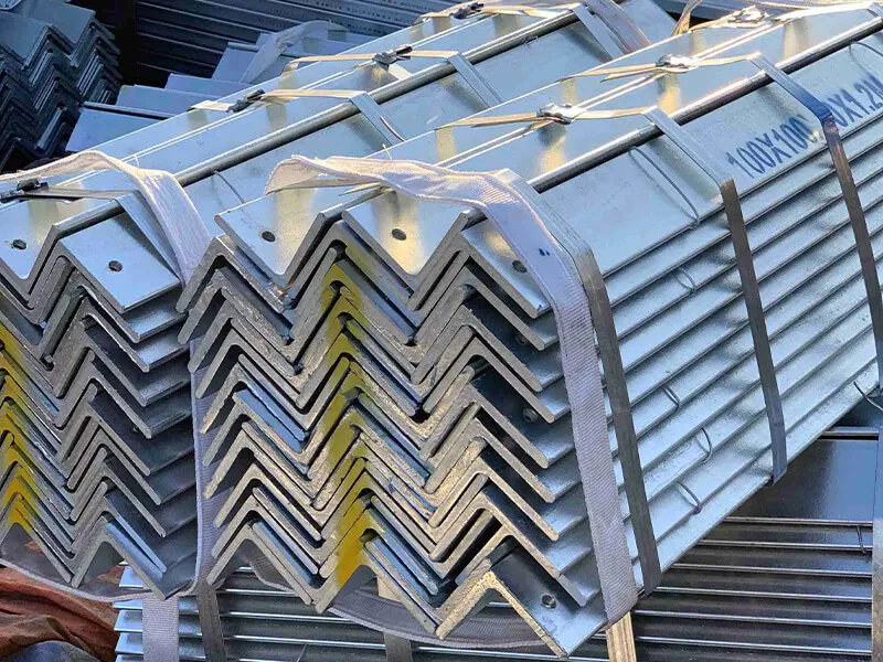
A final weld hides everything. It covers the gap you shimmed, the step you hammered down, and the twist you pulled out with a come-along. Six weeks later the surveyor finds it with a gauge, and by then the block is painted. So the check has to happen earlier, on the staging, with a gauge in hand and a pen in the other hand.
What Does Alignment Mean on a Marine Angle Steel Joint?
A fitter says the joint is aligned when the gap looks even. That is one of six relationships, and it is the only one the eye can judge.
Marine angle steel alignment covers six separate relationships: the bar’s own squareness, its position on the scribed line, the root gap, the high-low step at the mating face, the leg angle to the plate, and the continuity of the line along the panel. Each one needs its own gauge and its own tolerance.
When a joint fails in service, or fails a survey, the report rarely says “alignment”. It says lack of fusion at the root, or a crack initiating at a step, or a frame that sits 15 mm off the moulded line. All three started as a number nobody wrote down.
The Gap Is the Only Item That Announces Itself
Turn an angle bar against a plate and the root gap is right there in front of you. It is bright, it is open, and the welder can see it through the arc. That is why every crew checks it and almost no crew checks the step. But a 2 mm gap with a 4 mm step is a worse joint than a 4 mm gap with no step, because the step puts the load path through an offset and the weld toe lands on a stress riser. The gap is the loud item. The step is the quiet one.
Why the Bar’s Own Squareness Comes First
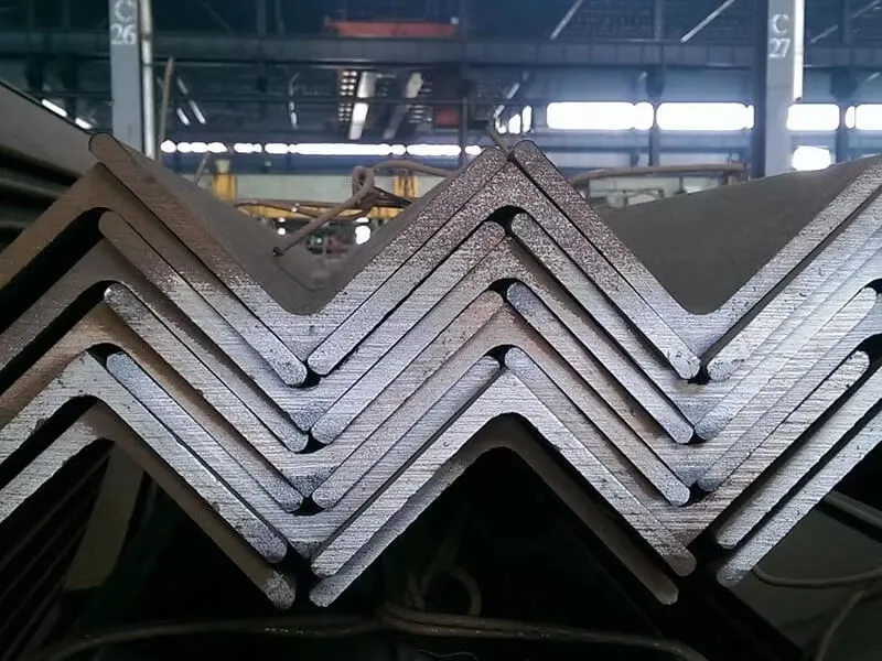
Before the bar touches the plate, it already has a shape error. EN 10056-2 allows an out-of-square deviation of 1.0 mm on angles up to 100 mm leg, 1.5 mm from 100 to 150 mm, 2.0 mm from 150 to 200 mm, and 3.0 mm above 200 mm. It also allows straightness deviation of 0.4 percent of length for legs up to 150 mm, which on a 12 m bar is 48 mm over the full length.
Read those two numbers together and the problem is obvious. A compliant bar can arrive with 3 mm of out-of-square, and the fit-up limit for a strength member is 3.0 mm. The steel has used the whole budget before your fitter has picked up a hammer.
The Line Is a Separate Item From the Joint
The sixth relationship is the one that belongs to the panel rather than to the joint. Each individual fillet can be inside tolerance while the stiffener line wanders across the plate, because every fitter’s joint was measured against the previous bar rather than against the scribed line. Ten joints later the frame is 20 mm off and the block will not close.
IACS handles this with a separate criterion, d ≤ L/50, for panel stiffener alignment. On a 6 m stiffener that is 120 mm, which tells you something useful: the class figure is a structural floor, not a workmanship target. No yard I have visited would accept a frame 120 mm off its line. They work to plus or minus 5 mm from the scribe and treat anything beyond it as a re-set. The rule tells you when the structure is at risk. Your own standard should tell you when the job is good.
| Alignment relationship | What it controls | Typical gauge | Who signs it off |
|---|---|---|---|
| Bar squareness (k) | Whether the leg sits flat | Square, feeler gauge | Receiving inspection |
| Set-out position | Frame spacing and moulded line | Tape, laser line | Foreman |
| Root gap (G) | Sidewall fusion at the root | Taper gauge | Welder, then QC |
| High-low step (a) | Stress path and toe profile | Straightedge, feeler, depth rule | QC |
| Leg angle to plate | Web alignment and buckling | Digital protractor | QC |
| Line continuity (d) | Panel fairness, block fit | String line, laser, scan | Block QC |
This is the point where I stop talking about steel and start talking about sequence. The section check has to happen at goods-in, not at the joint. If the bar is already out of square when it reaches the panel, the fitter’s only options are to force it, to grind it, or to send it back. Two of those three are wrong.
Which Tolerances Actually Decide Pass or Fail?
The numbers come from IACS Recommendation No. 47, the Shipbuilding and Repair Quality Standard, unless your project specification names something tighter.
For a butt joint the step limit is a ≤ 0.15t on strength members and a ≤ 0.2t on other members, with t taken as the thinner plate, and an absolute limit of 3.0 mm. For a fillet joint on an angle bar the height-direction offset is a ≤ 0.15t on primary members and a ≤ 0.20t on secondary members, limit 3.0 mm.

Most arguments on the staging are not about the rule. They are about which t to use, and whether the standard range or the limit range applies.
Read 0.15t With the Thinner Plate
Take an L100×100×10 angle welded to a 12 mm plate. The thinner of the two is 10 mm, so 0.15t is 1.5 mm, not 3 mm. Take an L75×75×6 on a 6 mm plate and the allowance falls to 0.9 mm. The 3.0 mm figure in the table is a ceiling for heavy sections, not a target for light ones.
That single misreading explains most of the fit-up disputes I have sat through. A fitter who has spent ten years on 20 mm blocks carries “three mil is fine” in his head, then moves to a 6 mm accommodation block and produces joints that are out of tolerance by a factor of three.
| Joint type | Member class | Standard | Absolute limit |
|---|---|---|---|
| Butt weld alignment | Strength | a ≤ 0.15t | 3.0 mm |
| Butt weld alignment | Other | a ≤ 0.2t, max 4.0 mm | 3.0 mm |
| Fillet weld alignment | Strength / high stress | a ≤ t1/3 on median | a ≤ t1/3 |
| Fillet weld alignment | Other | a ≤ t1/2 on median | a ≤ t1/2 |
| Angle bar height offset | Primary | a ≤ 0.15t | 3.0 mm |
| Angle bar height offset | Secondary | a ≤ 0.20t | 3.0 mm |
| Panel stiffener line | All | d ≤ L/50 | Per class |
| Bracket to stiffener gap | All | a ≤ 2.0 mm | 3.0 mm |
| Beam to frame gap | All | a = 2.0 mm | 5.0 mm |
Standard Range and Limit Range Are Not the Same Thing
Rec. 47 defines two bands. The standard range is what normal, competent work should produce. The limit range is the maximum deviation that can still be accepted. Work inside the limit but outside the standard is not automatically a pass; it is a decision, and on a strength member that decision belongs to the surveyor, not the fitter.
I have seen a yard treat the limit column as the acceptance criterion for every joint, because it kept the line moving. It worked until a newbuild had a run of brackets at 2.8 mm gap against a 2.0 mm standard. Nothing failed. But the surveyor wrote it up, the yard had to open 40 joints, and the schedule loss was far larger than the two hours of fit-up discipline would have cost.
Where the Mill Tolerance Eats Your Fit-Up Budget
The tolerances stack. A bar at the EN 10056-2 out-of-square limit, set 1 mm off the scribed line, with a 1 mm thickness variation between two heats, arrives at the joint with 3 mm of error already spent. Your fitter now has nothing left, and the joint is still cold.
| EN 10056-2 item | Range | Tolerance |
|---|---|---|
| Leg length | ≤ 50 mm | ± 1.0 mm |
| Leg length | 50 to 100 mm | ± 2.0 mm |
| Leg length | 100 to 150 mm | ± 3.0 mm |
| Thickness | ≤ 5 mm | ± 0.50 mm |
| Thickness | 5 to 10 mm | ± 0.75 mm |
| Out of square (k) | ≤ 100 mm leg | 1.0 mm |
| Out of square (k) | 100 to 150 mm leg | 1.5 mm |
| Straightness (q) | ≤ 150 mm leg | 0.4% of length |
| Mass per piece | t > 4 mm | ± 4% |
This is where the purchasing decision becomes a fabrication decision. A supplier who holds leg length to ± 1.0 mm and out-of-square to half the standard allowance is not selling you better steel for its own sake. He is selling you fit-up time. On a 600 tonne order, one millimetre of average out-of-square is worth more to your welders than a few dollars per tonne. You can see the same logic in our marine angle steel dimensional tolerances page, and it is the reason we publish a measurement sheet with each bundle rather than a certificate alone.
How Do You Measure Each Item on the Shop Floor?
You do not need a metrology lab. You need four tools, a flat surface, and the discipline to write the number down before the tack goes on.
Measure the root gap with a taper gauge at three points per metre and at both ends, the step with a straightedge and feeler gauge, the leg angle with a digital protractor, and the line with a string or laser. Record every reading against the joint number, then tack.
The tools are cheap. The habit is not.
The Taper Gauge Is the Only Honest Tool for Gap
A welder can look at a root gap and tell you it is “about three”. A taper gauge tells you it is 4.6 mm at the toe end and 2.1 mm at the heel end, which is a different problem entirely, because a taper means the bar is not parallel to the plate edge. That is a set-out error, not a gap error, and no amount of welding will fix it.
Measure at the two ends and at the middle of every joint, then at one metre intervals on anything longer than three metres. Write the smallest and largest value. The range matters more than the average.
| Tool | What it measures | Range | Where it fails |
|---|---|---|---|
| Taper gauge | Root gap | 0 to 10 mm | Deep bevels |
| Bridge cam gauge | Fillet leg and throat | 0 to 25 mm | Concave profiles |
| Feeler gauge set | Step and local bow | 0.02 to 1.00 mm | Steps above 1 mm |
| Straightedge, 1 m | Local straightness | Any | Long sweep |
| Nylon string | Full-length bow | Any | Twist |
| Digital protractor | Leg angle | 0 to 360 degrees | Very short legs |
| Laser line | Stiffener line over a panel | 10 m plus | Curved blocks |
| 3D scan | Whole block geometry | Block scale | Cost and setup time |
Measure Before Tacking, Then Again After
The first measurement is the one that decides. The second one is the one that saves you.
Tacking puts heat into a joint that is only held by clamps. A 40 mm tack on a 6 mm leg pulls the bar toward the tack side, and a joint that measured 1.2 mm can open to 2.4 mm by the time the last tack cools. If you only measure before tacking, you release a joint that is already out of tolerance. If you only measure after, you have no idea whether the error came from the fit or from the tack.
I learned this the expensive way on a Romanian order of L-shaped section steel for deckhouse frames [Zora will replace]. The fit-up sheet said pass. The welders said the gap kept opening. Both were right, because nobody measured the joint between the tack and the root pass.
Measure Cold, and Measure at One Temperature
Steel moves with heat, and a fit-up check taken on a bar that has just come off a plasma table is a measurement of something that will not exist in an hour. Cut a 12 m bar and the residual stress from rolling redistributes along the new free edge. The bar bows. Give it twenty minutes and it settles into a shape close to its final one.
The same logic applies to the panel. A deck panel checked in the morning sun and re-checked under a shed roof at night will read differently, and part of that difference is thermal, not dimensional. On a 6 m steel span, a 20 degree change is worth roughly 1.4 mm of movement at a coefficient of 12 by 10 to the minus 6 per degree [Zora will replace]. That is half your step allowance, spent on weather.
So measure after the steel has cooled, measure in the shade where you can, and if a reading looks strange, take it again before you act on it. A gauge is only honest when the thing it is touching has stopped moving.
Write the Numbers Down
A check that is not recorded did not happen. Put the joint number, the four readings, the date and the inspector’s initials on the traveler or on the joint itself in paint marker. When the surveyor asks why a frame sits 4 mm off the line three months later, the sheet answers the question in ten seconds.
This is also where a supplier’s paperwork earns its place. Gulf Metal Solutions came to us after a year of inconsistent surface finish and slow answers from other Chinese suppliers. What they asked for first was not a lower price. It was a dimensional sheet per bundle, so their receiving team could compare the steel against the same numbers we measured before loading. We send it with every marine angle steel shipment now, and their inspectors stopped guessing.
What Should You Do When the Check Fails?
The instinct on the staging is to pull the joint into place and weld it. That instinct is the reason a lot of ships have residual stress locked into their frames.
When alignment fails, do not pull it with a jack and weld under load. Re-cut and re-fit, heat straighten within an approved procedure, re-sequence the weld, or use an insert piece with class approval. A joint forced into place springs back when the restraint is cut and can crack at the root.
Pulling a joint closed pre-loads it. The weld then freezes that load into the structure. When the strongback comes off, the joint springs, the root sees tension it was never designed for, and the crack starts from the inside where nobody looks.
The Four Legitimate Repairs
Re-cut and re-fit is the cheapest on thin sections and the slowest on thick ones, because you lose the bar. Heat straightening works when the error is a bow or a twist rather than a gap, and it must follow the steel maker’s temperature limits; thermo-mechanically rolled plate has a ceiling well below what a free-hand torch will produce. Re-sequencing works when the error is angular, because welding the opposite side first pulls the leg back. An insert piece is the correct answer for a gap beyond the limit, and it needs class approval before you cut it.
What is never legitimate is filling a 12 mm gap with weld metal, shimming a butt joint, or grinding a high side below the minimum thickness. Each one converts a dimensional problem into a structural one, and the second is much harder to argue with a surveyor.
When to Stop and Call the Surveyor
Stop when the step exceeds 3.0 mm, when the root gap exceeds 5 mm on a standard butt preparation, when the repair needs an insert, or when the member is a strength member and the reading sits in the limit band rather than the standard band. Those four conditions are not fitter decisions. They are documented decisions, and the documentation is what protects the yard at delivery.
| Condition found at the check | Wrong reaction | Correct action | Who approves |
|---|---|---|---|
| Root gap over 5 mm | Fill with weld metal | Re-cut, or insert piece | QC, then class |
| Step over 3.0 mm | Pull with a jack and weld | Re-fit, or heat straighten | QC |
| Bar out of square at goods-in | Grind the leg | Reject the bar, claim the heat | Receiving, then supplier |
| Tapered gap along the joint | Weld from the tight end | Re-set the bar parallel | Foreman |
| Twist across a 12 m bar | Clamp and tack | Heat straighten, or re-cut | QC |
| Line off by 6 mm over 6 m | Accept it as “close enough” | Re-scribe and re-set | Foreman and QC |
The last row is the one that costs the most, because it is the one nobody argues about. Six millimetres sounds like nothing on a 6 m frame. Then the next frame copies it, the block goes together 12 mm out, and the erection crew spends a shift with a gas torch and a port-a-power correcting something that a chalk line would have caught for free.
Conclusion
Measure the six relationships before the tack, write the numbers down, and treat the limit range as a decision rather than a target. Alignment is cheaper before the arc than after the paint.