
Fit-up gaps in marine angle steel sections stall welders, fail surveyors, and push schedules back. Most causes trace back to decisions made long before the welding arc even lights.
Most fit-up problems in marine angle steel sections come from four sources: rolling tolerances in the section itself, inaccurate cutting and edge preparation, cumulative alignment errors across fabricated blocks, and force-fitting during erection. Measuring every batch against IACS Rec. 47 tolerances before assembly removes nearly all of them.
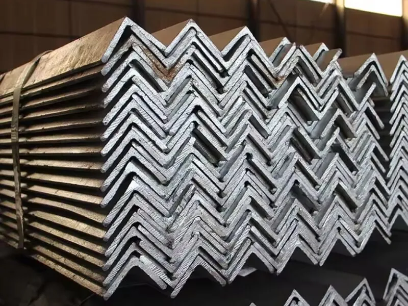
I talk with fabrication supervisors almost every week, and fit-up is the topic that keeps coming back. A frame that looks fine on the truck can still refuse to sit flush on the panel line. The section is rarely the only guilty party, but it is where the investigation should start, because every error that enters the assembly with the angle bar gets locked in permanently by the first weld. Welding does not correct mistakes; it preserves them. So before blaming the welders, walk the problem backwards through the four stages below. In my experience, that walk usually finds the cause in under an hour.
Why Does the Section Itself Arrive Out of Tolerance?
Hot-rolled marine angle steel leaves the mill with small deviations in leg length, thickness, straightness, and twist. Each one seems harmless on paper. Together, they turn a clean drawing into a gap that no welder can close.
Rolling tolerances allow a legitimate section to be slightly out of square, cambered, or twisted. IACS Rec. 47 accepts a 0.2% straightness deviation as standard and recommends holding it to 0.1%. A 12 m bar at 0.2% carries up to 24 mm of bow — enough to open a visible gap at the bracket every time.
Leg Length and Thickness Tolerance
Angle sections are rolled hot, and hot rolling breathes. The standards recognise this: leg length and web thickness carry tolerances that allow a delivered bar to differ modestly from the nominal size. A 100×100×10 angle that measures 10.4 mm on one leg and 9.6 mm on the other is still a conforming bar. But set two of those bars back to back for a butt weld and the unequal legs produce a mismatched surface line that shows up immediately in the alignment check.
The practical damage is subtle. A fitter clamps the first bar to the frame line and it sits perfectly. The next bar from the same bundle sits 1 mm proud. The one after that sits 1 mm low. Each bar is within tolerance; the assembly now contains a staircase. When the surveyor measures alignment across the joint, the deviation limit for strength members is tight, so the staircase has to be ground or reworked. I have watched crews waste half a shift chasing a mismatch that was baked into the bundle at the rolling mill.
The fix is not to reject the steel — the tolerance is contractual and normal. The fix is to check and sort. At our warehouse in Liaocheng we measure a sample of legs from each bundle with a calliper before dispatch, and I encourage buyers to do the same on arrival. Ten minutes of sampling beats a week of fairing.
Straightness, Camber, and Twist
Straightness is where fit-up problems get expensive. IACS Rec. 47 sets the standard tolerance for structural member straightness at 0.2% of the length, with 0.1% recommended for good practice. On a 12 m angle bar, 0.2% means up to 24 mm of bow; 0.1% means 12 mm. Now think about a transverse frame that must land on a bracket face with a gap of 2 mm or less, which is the Rec. 47 standard for bracket-to-stiffener fit. A bar carrying even the recommended camber will not close that gap at both ends without help.
Twist is worse than camber because it attacks the squareness of the leg face as well as the line of the bar. A twisted angle rocks on its legs. When fitters pull it down against the panel, the section takes a permanent set or springs back after the clamps come off, and the tack welds crack overnight. That is the classic “the frame was fine yesterday” complaint, and it almost always traces to twist rather than to the tacks.
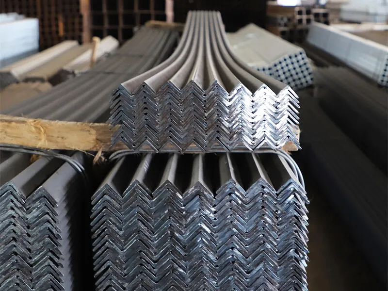
There is also a sourcing dimension to straightness that buyers control directly. Bars transported loose in containers arrive far more twisted than bars shipped in secured bundles on breakbulk vessels, because loose bars slide and lever against each other at sea. We bundle our angle steel in strapped lots with timber separators, and the difference shows up on the customer’s straight edge the day it arrives. If your supplier’s packing looks casual, your fit-up will look worse. It is a small thing to ask for in the purchase order, and it costs nothing compared with the fairing work it prevents.
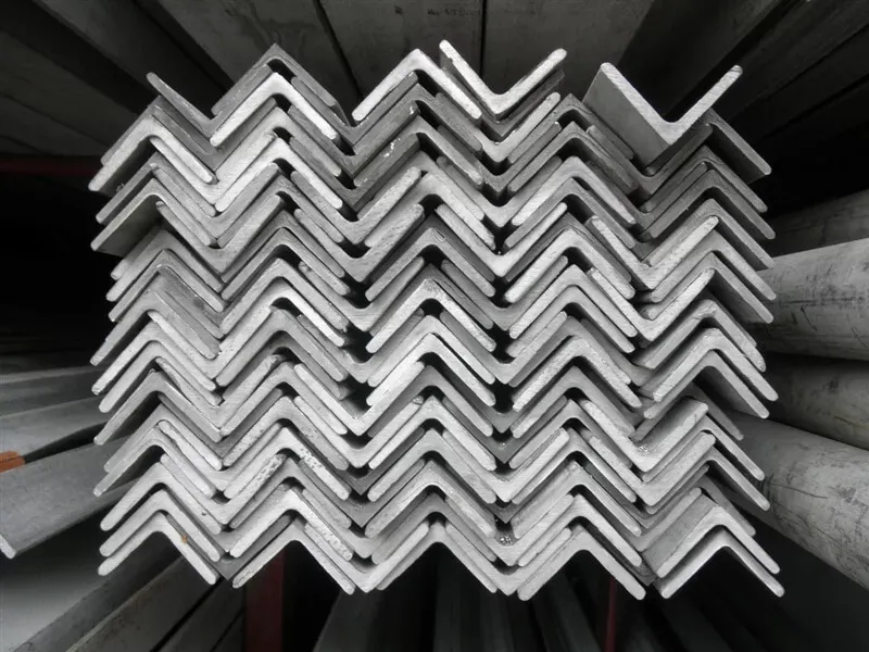
My own rule after years of loading breakbulk shipments: any bar you can see bowing along its length from two metres away will fight you at fit-up. Send it back for straightening before it reaches the assembly floor, not after the surveyor finds it.
| Deviation in the delivered bar | What it does at fit-up | Rec. 47 reference value |
|---|---|---|
| Leg length out of tolerance | Mismatched surface line across butt joints | Alignment a ≤ 0.15t for strength members |
| Web thickness variation | Unequal fillet sizes, root gap drift | Standard bracket gap ≤ 2.0 mm |
| Camber / straightness 0.2% of length | Open ends, gap at bracket faces | 0.1% recommended; 24 mm max on a 12 m bar |
| Twist | Leg faces not square, bar rocks on clamps | Excessive force in assembly is prohibited |
| Length short of nominal (e.g. −20 mm) | Frame falls short of the bracket | Length tolerance ±50 mm still accepts it |
Do Cutting and Edge Preparation Errors Start the Problem?
The section can be perfect and the fit-up can still fail, because the cut face is where the joint actually lives. Kerf drift, bevel angle error, and rough edges each contribute their share to the final root gap.
Cutting and edge preparation control the root gap, and the root gap is the single most inspected fit-up dimension. IACS Rec. 47 sets a standard maximum of 3 mm for closed square grooves and 3–9 mm for single-V joints on backing, so a 2 mm kerf error can consume most of the allowance on its own.
Root Gap and the Rec. 47 Limits
Every fit-up inspection ends at the same question: what is the gap? Rec. 47 gives the answer frame. A closed square-groove butt joint on thin material is standard at 3 mm or less, with 5 mm as the absolute limit. A single-V preparation welded on a backing bar is more forgiving — 3 to 9 mm standard, up to 16 mm at the limit — because the backing carries the root. Between those two cases sits almost every fit-up dispute I have seen.
The mechanism is arithmetic. Take a 3 mm allowance and a band saw that wanders 2 mm off the line, then add a bevel ground at the wrong angle that adds another millimetre of effective opening. The joint is now at or beyond the limit before a welder touches it. The crew then has two choices: rebuild the joint, or weld it over-gapped and hope the surveyor accepts a repair procedure. Neither is cheap, and both show up in the schedule.
Good shops make the gap measurable before the bar arrives at the panel. Cut a sample, check the root gap against a wedge gauge, and adjust the machine before committing the whole cut list. The handful of minutes spent on a first-article check is the cheapest quality insurance in the workshop. This is the same discipline our client Gulf Metal Solutions applies in Dammam — they check first articles before their fabricators commit full lengths, and their rework rate is visibly lower than the regional average.
Bevel Angle and Edge Quality
A bevel cut at the wrong angle creates a gap that widens or narrows along the joint. The root may sit at 2 mm while the face sits at 6 mm, and the welder cannot make one arc follow both. Bevel angle errors usually come from worn guides, rushed torch manipulation, or a bevel laid out by hand instead of machined.
Edge quality matters just as much. Class surveyors check cut edges for notches, and CCS surveyor guidance is explicit that cut edges should be smooth, with notches ground out rather than welded over. Heavy dross on a plasma-cut edge also blocks the close contact that a closed joint needs. When the fitter forces a rough edge against its partner, the contact points carry the load and the real gap hides between them, only to open up once the tack welds shrink.
The practical sequence I recommend is simple: machine the bevel, deburr and grind the cut face bright for 20 mm, blow off the dust, then measure the gap with a gauge at both ends and mid-span. If those three readings differ by more than the allowance, correct the cut, not the fit.
| Joint preparation | Standard root gap | Absolute limit | Typical failure when exceeded |
|---|---|---|---|
| Closed square groove, t ≤ 5 mm | ≤ 3 mm | 5 mm | Burn-through, lack of fusion at root |
| Single-V on backing bar | 3–9 mm | 16 mm | Excess weld metal, distortion |
| Fillet lap / bracket fit | ≤ 2 mm gap | 3 mm | Weakened fillet, surveyor hold point |
| Stiffener through cutout clearance | ≤ 2 mm | 3 mm | Cracked collar weld later in service |
How Do Block Joints Turn Small Errors into Big Fit-Up Failures?
Even a perfect bar and a perfect cut can fail at the block joint, where the alignment of two fabricated halves meets. Errors accumulate across panels and blocks, and the joint between them is where the bill arrives.
At block erection, alignment errors from every earlier stage arrive together. Rec. 47 limits face alignment to 0.15t for strength members and gives angle and bulb profiles 3 mm as the practical limit in height, so a 10 mm frame offset across a block joint is far outside any accepted standard.
Cumulative Misalignment Across the Joint
In double-bottom and side-block erection, the angle bars and stiffeners on two adjoining blocks are supposed to meet face to face. In practice they rarely do on the first try. Each block was built from panels that carried their own tolerances, welded with their own shrinkage, and stacked through their own jig errors. The angle joint at the erection seam collects all of it. The classic failure is height offset: one face sits high, the other low, and the welder is asked to bridge a step.
The Chinese shipbuilding literature describes this exact problem for double-bottom blocks, where angle bars on the two halves do not lie in the same plane and crews historically adjusted them by welding clips and tabs onto the bars, then cutting the clips away afterwards. That practice leaves scars in the parent metal and damages the coating systems in ballast tanks, which is precisely why newer methods use reusable clamping fixtures and jacks instead.
Rec. 47 quantifies what is acceptable: butt alignment within 0.15t for strength members, fillet-weld alignment within a third of the thinner leg, and for T-bars, angles, and bulb profiles a standard height alignment of 3 mm. When the measured offset is 8 or 10 mm, no amount of persuasion makes it conformable — the joint has to be corrected by a documented repair method, and the surveyor signs it off before welding starts.
Force-Fitting and Its Limits
The temptation at every misaligned joint is to pull it closed. Jacks, clips, and chain blocks can bring almost anything into contact — that is the problem. Forcing a bar into position loads it with elastic stress that stays in the structure after the weld is finished, and the guidance is blunt about it: excessive force in assembly is prohibited, and distorted members should be corrected before the next assembly stage, not wrestled into place.
Class guidance adds a thermal caution on top of the mechanical one. When correction means flame straightening, the heating temperature on high-strength steel should not exceed 650 °C, and repeated flame correction at the same spot can change the material properties enough that the surveyor asks for tests — or rejects the member outright. So the repair menu is short, and every item on it needs a procedure rather than a strong back.
The stress does not stay quiet. When the weld shrinks, the stored stress releases unevenly and the assembly moves — bars bow, tacks crack, and panel lines that were checked and approved drift out of tolerance overnight. I have heard this story from more than one yard: the frame passed fit-up at 17:00 and failed at 07:00 with nobody near it. The culprit was force, not magic.
There is also a repair-cost angle. Jacking a misaligned profile flat often just hides the problem until it reappears during welding, at which point the fix is bigger. The comparison below sums up the realistic options, and the pattern across them is consistent: the earlier and more deliberate the correction, the cheaper it is. When we ship angle steel to yards in Saudi Arabia and Vietnam, this table is the conversation I have with the fabrication lead before the first bar lands, because choosing a correction method under time pressure always costs more than choosing it in advance.
| Correction method at a misaligned angle-bar joint | Best for | Main risk | Relative cost |
|---|---|---|---|
| Jacking / force-fitting | Small offsets within tolerance | Stored elastic stress releases after welding | Lowest, but false economy |
| Single-side build-up weld, then trim | Moderate height offset on a web | Long weld removal work, poor line quality | Medium |
| Cut, bend, and re-weld the profile end | Larger offsets with a planned procedure | Needs heat control and re-inspection | Medium-high |
| Remove member and re-fit new material | Offsets beyond any repair standard | Schedule impact, coating damage | Highest |
A last word from the dockside. At a yard I visited [Zora will replace: location], I watched a crew spend a full morning jacking a frame line square, weld it, and watch it spring back by lunch. The foreman’s comment stayed with me: “the steel was honest, the schedule wasn’t.” Fit-up problems are rarely mysterious. They are the visible end of tolerances nobody measured, cuts nobody checked, and forces nobody should have applied. Buy section steel that arrives straight, cut it like you mean to inspect it, and never close a gap with force — that is the whole discipline in three sentences.
Conclusion
Fit-up failures in marine angle steel come from rolling tolerance, cutting error, accumulated misalignment, and force-fitting. Measure against IACS Rec. 47 at every stage and the gaps close themselves.