
Are you tired of choosing between heavy structures that cost too much and lighter ones that fail too soon? Many engineers face this exact problem every day. They need strength but also want to save weight and money. The solution lies in a smart material choice and design strategy.
To optimize structural strength using bulb flat steel, you need to focus on four key areas: understanding its stiffness-to-weight advantage, placing it in the right direction, using it to resist buckling, and ensuring strength continues at joints. When you do these things correctly, you get a structure that is both strong and light.
But knowing the theory is not enough. You need practical steps that work in real shipyards and construction sites. Over the last ten years, I have helped dozens of projects in Vietnam, Mexico, and Saudi Arabia get their steel right. Let me share what I learned from those experiences. We will go deep into each area so you can apply these ideas immediately.
The Anatomy of Efficiency: Why Bulb Flats Excel in Stiffness-to-Weight Ratio?
You might think that adding more steel is the only way to make something stronger. But that approach increases weight and cost. Worse, it makes your vessel or structure less efficient. You need a better way.
Bulb flats excel in stiffness-to-weight ratio1 because of their unique shape. The rounded bulb at one end adds material exactly where it is needed most. This increases the moment of inertia2 without adding much weight. Compared to flat bars or angles, bulb flats3 give you more stiffness per kilogram.
Understanding the Mechanics Behind the Shape
Let me break down why this shape works so well. In structural engineering, stiffness comes from how far the material is from the center of the section. This distance is called the radius of gyration. The bulb flat has most of its mass concentrated in the bulb, which is far from the neutral axis. This gives it a high moment of inertia. Meanwhile, the web part connects the bulb to the plate and distributes loads evenly.
I remember a project in 2019 for a shipbuilder in Thailand. They were using flat bars as stiffeners on a bulk carrier. The design was okay, but they wanted to reduce the hull weight to increase cargo capacity. We ran some calculations together. By switching to bulb flats of equivalent stiffness, they saved 12% on steel weight4. That meant they could carry more cargo on every trip. The ship owner was very happy.
Comparing Bulb Flats with Other Common Profiles
To make this clear, look at the table below. It compares the stiffness-to-weight ratio for three common profiles used in shipbuilding. The numbers are based on typical sizes used for similar applications.
| Profile Type | Weight per Meter (kg) | Moment of Inertia (cm⁴) | Stiffness-to-Weight Ratio (cm⁴/kg) |
|---|---|---|---|
| Flat Bar 200×10 | 15.7 | 133 | 8.5 |
| Angle Steel L100x75x7 | 9.4 | 89 | 9.5 |
| Bulb Flat 160×6 (with bulb) | 12.1 | 210 | 17.4 |
As you can see, the bulb flat provides much more stiffness for each kilogram of steel. This is not a small difference. It means you can use smaller, lighter sections and still meet the strength requirements. In practical terms, this translates to lower material costs, easier handling during construction, and better performance of the final structure.
Why Material Quality Matters
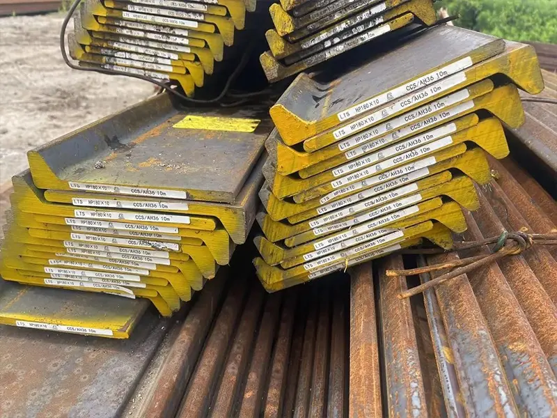
Of course, the shape alone is not enough. The steel itself must be consistent and reliable. In our work at CN Marine Steel, we only source from mills that are certified. We have long-term partnerships with these mills. This ensures that every bulb flat we deliver has the correct dimensions and mechanical properties. I have seen cases where cheap material from unknown sources had variations in the bulb size. That small difference can reduce the stiffness by 10% or more. Always insist on SGS or third-party inspection5 to verify the quality.
Strategic Placement: Optimizing Bulb Flat Orientation for Maximum Load-Bearing Capacity?
Imagine you have the best bulb flats1 in your warehouse. But if you install them in the wrong direction, you waste their potential. Many designers treat stiffeners as simple add-ons without considering how loads actually flow through the structure.
To maximize load-bearing capacity2, you must align bulb flats with the primary direction of the load. For longitudinal strength3, such as in a ship hull, place them running from bow to stern. For local loads, like on a deck, orient them perpendicular to the supporting girders. Getting this right can double the effective strength of your structure.
The Science of Load Paths
Every structure has a load path. Forces travel through the material from the point of application to the supports. Stiffeners should be placed along these paths. When you put a bulb flat in the right orientation, it acts like a beam, carrying bending loads efficiently. If you put it the wrong way, it might twist or bend in a direction where it is weak.
Consider the bottom of a ship. The water pressure pushes up on the hull. The main strength members are the longitudinal girders and the stiffeners attached to the bottom plate. If you run bulb flats transversely (across the ship), they will not help much against the overall bending of the ship. But if you run them longitudinally, they become part of the main strength system.
Longitudinal vs. Transverse Placement: A Practical Example
I once worked with a contractor in Qatar who was building a set of oil tankers. They had a design that used angle steel for both longitudinal and transverse stiffeners4. During a review, we noticed that the longitudinal stiffeners on the bottom were quite heavy angles. I suggested we could replace them with bulb flats and save weight. But we also had to check the transverse stiffeners. In some areas, transverse stiffeners are needed to support the longitudinal ones and prevent buckling5. The orientation decision is not always simple.
Let me show you a simple comparison. The table below gives typical applications for each orientation.
| Orientation | Primary Function | Typical Location | Example Load |
|---|---|---|---|
| Longitudinal | Resist global bending | Bottom, deck, side shell | Hull girder bending |
| Transverse | Resist local bending and support longitudinals | Bulkheads, web frames | Water pressure on bulkhead |
In the Qatar project, we ended up using bulb flats for the longitudinal stiffeners and a combination of bulb flats and L-shaped sections for the transverse ones. We optimized each location based on the load direction. The result was a lighter hull that still passed all the classification society checks.
Common Mistakes and How to Avoid Them
One mistake I see often is ignoring the orientation at intersections. For example, where a longitudinal stiffener crosses a transverse web, there needs to be a proper connection. If the bulb flat is cut or notched incorrectly, the strength drops dramatically. Always think about the whole system. Use continuity where possible, which leads us to the next topic.
Buckling Resistance Mastery: Using Bulb Flats to Prevent Local Failure?
Buckling is a silent killer in steel structures. It happens suddenly, without warning. One moment the plate is flat, the next it wrinkles and folds. This is especially dangerous in ships and tanks where the loads are high and the plates are thin.
Bulb flats1 prevent local buckling by providing rigid support along the edges of plates. The bulb acts like a small built-in edge stiffener. It increases the critical buckling stress2 of the plate panel. This allows you to use thinner plates without fear of failure, saving weight while maintaining safety.
Understanding Buckling Modes
There are different types of buckling. The most common in stiffened panels is plate buckling3. This is when the plate between stiffeners buckles under compression. The stiffeners themselves can also buckle, either overall or locally. Bulb flats help in two ways. First, they divide the large plate into smaller panels, which are more stable. Second, their bulb shape resists twisting, so they stay straight and continue to support the plate.
I remember a case from a few years ago. A customer in Malaysia was building a barge. They used flat bars as stiffeners on the bottom. During a trial, they noticed some deformation. We analyzed it and found that the flat bars were too flexible. They twisted under load, allowing the plate to buckle. We recommended replacing them with bulb flats of the same height. The bulb prevented twisting, and the problem was solved.
How Bulb Flats Compare in Buckling Resistance
Let me put some numbers to this. The critical buckling stress depends on the slenderness of the plate and the stiffness of the edge supports. Bulb flats provide a much stiffer edge support than a simple flat bar. The table below compares the effectiveness of different stiffener types4.
| Stiffener Type | Torsional Stiffness | Relative Buckling Capacity of Plate |
|---|---|---|
| Flat Bar | Low | 1.0 (baseline) |
| Angle Steel | Medium | 1.3 |
| Bulb Flat | High | 1.6 |
These are approximate values based on our experience. The actual improvement depends on the exact dimensions. But the trend is clear. Bulb flats give you the best resistance against buckling for a given weight.
Design Tips for Maximum Buckling Resistance
When you design with bulb flats, follow these simple rules:
- Keep the spacing between stiffeners small enough. The plate will buckle if the panel is too wide. A good rule is to keep the width-to-thickness ratio5 of the plate below a certain value. Classification societies have formulas for this.
- Make sure the bulb flat itself does not buckle. The bulb provides good torsional stability, but you still need to check the web height. If the web is too tall and thin, it can buckle locally. Use standard sections that are proven.
- At supports, provide enough connection to prevent the stiffener from rotating. This is often done by welding the bulb flat to a transverse web or a bulkhead.
We always support our customers with these calculations. If you send us your design, we can help you select the right bulb flat size. We have done this for clients in Romania and the Philippines. It saves them time and ensures the structure is safe.
Continuity Matters: Design Strategies for Uninterrupted Strength at Joints?
No structure is one single piece. We have to join sections together. But every joint is a potential weak point. If you do not handle it carefully, the strength you built into the stiffeners disappears at the connections.
To maintain strength at joints, you must ensure that bulb flats are continuous through the connection or properly splice1d. This means aligning the stiffeners on both sides of a joint and providing adequate overlap or welded connections2. Interrupting the bulb flat without reinforcement creates a stress concentration that can lead to cracks.
The Problem with Interrupted Stiffeners
Imagine a longitudinal stiffener that runs along the bottom of a ship. It comes to a transverse bulkhead. If you cut the stiffener at the bulkhead and do not connect it, the stiffener stops. The load it was carrying has to find another path. This creates high stresses at the bulkhead connection. Over time, fatigue cracks3 can start.
I saw this issue firsthand with a client in Pakistan. They were building a series of container ships. The design called for bulb flats on the side shell. At the transverse bulkheads, the stiffeners were cut and only welded to the bulkhead plate. After a few years in service, cracks appeared at the toes of the welds. We investigated and found that the lack of continuity was the cause. The solution was to modify the design so that the bulb flats passed through the bulkhead with proper slots, or to add strong brackets.
Techniques for Ensuring Continuity
There are several ways to handle joints. The best is to pass the stiffener through the joint. In shipbuilding, this means cutting a slot in the transverse member and welding the stiffener as it passes through. This maintains the full strength. But it requires careful fitting.
Another method is to use a splice. If you have two pieces of bulb flat that meet end-to-end, you can weld them together with a full penetration weld. This is common when joining sections of a ship. The weld must be strong enough to transfer the load. We always recommend using a backing bar or a temporary support to ensure good alignment.
Sometimes you have to change direction. For example, at the intersection of a longitudinal and a transverse, you might use a bracket. The bracket connects the two and spreads the load. The table below shows common joint types and their effectiveness.
| Joint Type | Description | Strength Continuity | Ease of Construction |
|---|---|---|---|
| Continuous (slot) | Stiffener passes through a slot in the intersecting member | 100% | Medium |
| Butt Weld | End-to-end weld with full penetration | 90-100% | High |
| Lap Joint | Overlap and weld on both sides | 70-80% | High |
| Bracketed | Stiffener ends at intersection, connected with a bracket | 50-70% | Low |
Practical Advice from Our Experience
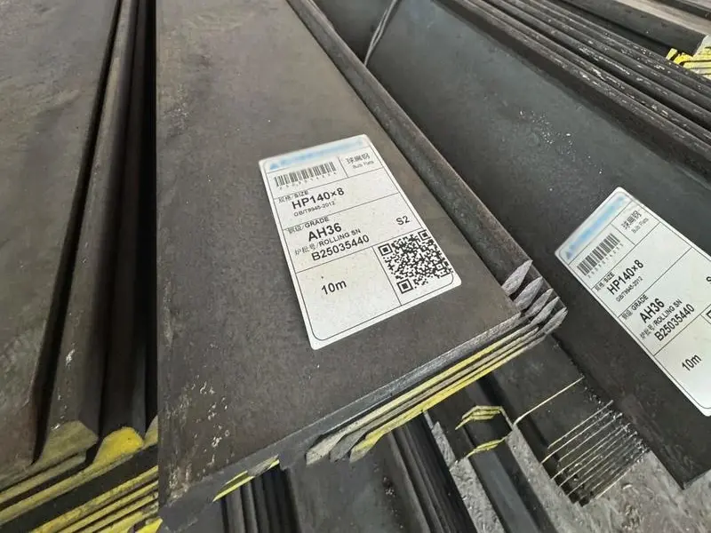
When we ship bulb flats to customers, we always remind them to plan for continuity. In our packaging, we mark each piece clearly so that the steel arrives in good condition. We also provide mill certificates that show the exact dimensions. This helps the fabricators fit the pieces accurately.
One tip I often share: when you order bulb flats, order extra length so you can make the continuous runs without too many splices. Splices take time and can be weak points. It is better to have longer pieces and cut them to fit. We can supply lengths up to 12 meters, sometimes longer if arranged. Talk to us about your project needs.
Conclusion
Optimizing structural strength with bulb flat steel comes down to four actions: choose it for its high stiffness-to-weight ratio, place it along the load direction, use it to resist buckling, and keep it continuous at joints. Follow these steps and your structure will be both strong and efficient.
-
Discover effective splicing techniques to ensure strong joints and maintain structural integrity. ↩ ↩ ↩ ↩
-
Understanding welded connections is essential for achieving strong and durable joints in ship structures. ↩ ↩ ↩ ↩
-
Explore the causes of fatigue cracks to prevent structural failures and enhance ship longevity. ↩ ↩ ↩ ↩
-
Gain insights into various stiffener types and their effectiveness in structural applications. ↩ ↩ ↩
-
Understanding this ratio is crucial for ensuring the stability and safety of structural elements. ↩ ↩ ↩