
You know L‑shaped steel is used in ships. But where exactly does it go? And why is that shape so common on decks and frames?
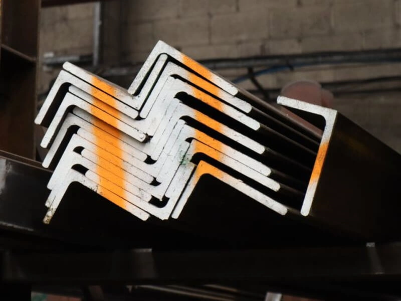
Marine L‑shaped steel (angle steel) is used as deck beams, transverse frames, longitudinal stiffeners, and built‑up assemblies. Its 90‑degree shape provides high bending stiffness for the weight. It is easy to weld into place and connect with other parts.
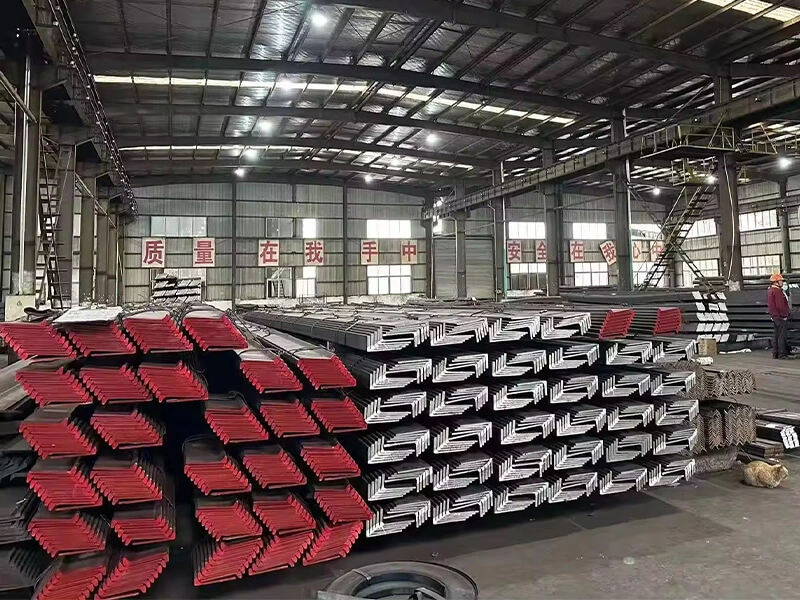
I am Zora Guo from cnmarinesteel.com. I supply marine angle steel to shipyards and wholesalers worldwide. Many customers ask me: “How exactly do you use L‑shaped steel in a ship?” Today I will walk you through the main applications. You will see why this simple shape is so valuable for deck and frame structures.
How Are L‑Shaped Sections Used as Deck Beams and Transverse Frames to Support Deck Plating and Reduce Weight?
You put a heavy cargo on the deck. The deck plate alone would bend. So you need beams underneath. These beams are often L‑shaped steel.
L‑shaped sections work as deck beams and transverse frames by sitting under the deck plate with one leg welded flat to the plate. The other leg sticks down to give bending strength. This shape supports the deck while using less steel than a flat bar of the same stiffness. That reduces the ship’s weight.

Let me explain how this works in real shipbuilding.
Deck Beams – The Hidden Support
On a ship’s deck, you walk on the steel plate. But that plate is only 8‑12mm thick. Without support, it would flex like a trampoline. So shipbuilders weld beams underneath. These beams run from one side of the ship to the other (transverse direction). Or sometimes they run along the length (longitudinal). For smaller and medium ships, L‑shaped steel is very common for these beams.
How an L‑shape deck beam is installed:
- The beam is an L‑section, for example L150x90x12.
- One leg (the longer leg, 150mm) is welded flat against the underside of the deck plate.
- The other leg (90mm) hangs down vertically.
- The vertical leg gives the beam its bending strength.
- The horizontal leg spreads the load along the plate.
Why L‑shape instead of a flat bar?
- A flat bar of the same weight would be much weaker in bending.
- A flat bar would also be harder to weld because you only have one narrow edge to weld.
- The L‑shape gives you a wide, flat surface for welding.
Transverse Frames – The Ribs of the Hull
Transverse frames are like ribs that run vertically (or slightly angled) along the side shell of the ship. They connect the bottom structure to the deck. L‑shaped steel is widely used for these frames on smaller vessels like fishing boats, tugboats, and coasters.
Typical arrangement:
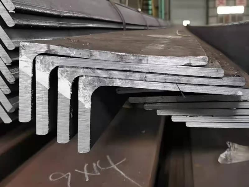
- The frame is an L‑section placed with one leg against the side shell plate.
- The other leg points inward toward the center of the ship.
- Frames are spaced every 500‑700mm along the length.
- The bottom of the frame is connected to the floor (bottom structure).
- The top of the frame connects to a deck beam.
I visited a shipyard in Vietnam that builds 40m fishing vessels. They used L200x100x14 for their main transverse frames. The naval architect told me: “We tried using bulb flat for these frames on one boat. It saved 7% weight. But the welders took longer. The cost per frame was higher. We switched back to L‑sections on the next boat.”
Weight Reduction Comparison
Let me show you the weight difference between using flat bar and L‑section for the same stiffness.
| Profile | Size | Weight per meter | Bending stiffness (relative) | Weight for same stiffness |
|---|---|---|---|---|
| Flat bar | 150 x 15mm | 17.7 kg | 1.0 (baseline) | 17.7 kg |
| L‑section (equal leg) | 150 x 150 x 10mm | 23.1 kg | 2.3 | Not same stiffness, but stronger. |
| L‑section (unequal leg) | 150 x 90 x 12mm | 21.3 kg | 1.7 | To match flat bar stiffness, you could use a smaller L‑section. |
If you only need the stiffness of a 150×15 flat bar, you might use L100x100x8 (weight 12.2 kg/m). That is 31% lighter. So L‑sections really do reduce weight.
What Role Do L‑Sections Play as Longitudinal Stiffeners Along Deck, Bottom, and Side Shell for Hull Strength?
You want the ship to be stiff along its length. Bending waves from front to back can stress the hull. You need long steel members running the full length of the ship.
L‑sections act as longitudinal stiffeners by running continuously along the deck, bottom, and side shell. They work together with the outer plate to resist the overall bending of the ship. This makes the hull stronger without adding too much weight.
Longitudinal stiffening is very important on larger ships. Let me break it down.
How Longitudinal Stiffening Works
Imagine a ship as a long hollow beam. The top of the beam (deck) and the bottom of the beam (bottom shell) take the most stress when the ship bends. You want those areas to be stiff. So you weld long steel profiles to the inside of the deck and bottom plates. These are longitudinal stiffeners.
Common locations for L‑shaped longitudinal stiffeners:
- On the inner bottom – under the cargo hold floor.
- On the underside of the deck – especially on tankers and bulk carriers.
- On the side shell – in the double side tanks (if present).
Why L‑section works well for this job:
- The shape gives good bending strength in the vertical direction (to resist the ship’s bending).
- L‑sections are easy to cut to exact lengths (up to 12-15 meters from the mill, or butt-welded longer).
- They allow space for welding from both sides.
Comparison with Other Stiffener Profiles for Longitudinal Use
| Profile | Strength‑to‑weight | Ease of connection at ends | Availability | Best for |
|---|---|---|---|---|
| L‑section (angle) | Good | Very easy (cut and weld) | Excellent | General longitudinal stiffening on medium ships |
| Bulb flat | Excellent | Moderate (need special end prep) | Lower | Large ships where every ton matters |
| Flat bar | Poor | Easy | Excellent | Light stiffening only |
| Tee section | Very good | Moderate (more complex cuts) | Moderate | High‑load areas |
Real Example – A Bulk Carrier
I supply L‑section steel to a customer in Malaysia who builds bulk carriers (50,000 DWT). On these ships, the double bottom is stiffened with longitudinal L‑sections. They use L200x100x15 and L250x100x16. The spacing is about 800mm. The L‑sections run from the forward collision bulkhead to the aft peak bulkhead, a distance of nearly 180 meters. They are butt‑welded together from 12m pieces.
The head engineer told me: “We used bulb flat on our first ship. It was fine. But the lead time was long. For our second ship, we switched to L‑sections. The welding is faster. We finished the double bottom two weeks earlier. The weight difference was only 3%.”
Effect on Hull Strength
Longitudinal stiffeners increase the hull’s section modulus. That is a measure of how well the hull resists bending. Each L‑section adds its own moment of inertia. The combined effect is significant.
A quick formula (simplified): For a deck with stiffeners spaced 800mm apart, the effective strength is roughly the plate plus the stiffener working together. An L125x80x12 stiffener can increase the local section modulus by 2-3 times compared to plate alone.
How Are L‑Shaped Steel Members Welded into Built‑Up Frame Assemblies for High‑Load Areas?
Sometimes a single L‑section is not strong enough. The load is too high. For example, around a large hatch opening or near the engine room. You need a stronger structure.
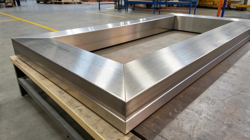
In high‑load areas, shipbuilders weld two or more L‑shaped members together to form built‑up assemblies. Common examples are a built‑up beam (two L‑sections back to back) or a reinforced frame (L‑section with a face plate). These assemblies handle much higher loads than a single L‑section.
Let me show you the most common built‑up assemblies using L‑sections.
Assembly 1: Back‑to‑Back L‑Sections (Built‑Up Tee)
Take two L‑sections of the same size. Weld them together along their outstanding legs (the legs that are not against the plate). The result looks like a T (or a + shape). This assembly is very strong in bending in all directions.
How it is made:
- Two angle bars, say L150x90x12.
- Place them with the 150mm legs together and the 90mm legs pointing outward.
- Weld along the contact line between the two 150mm legs.
- This creates a symmetrical beam with two outstanding flanges.
Where used:
- Strong deck beams under heavy cranes.
- Frames around large openings (cargo hatches).
- Support structures for machinery.
Assembly 2: L‑Section with Face Plate
Take one L‑section. Weld a flat bar (or another L‑section leg) onto the tip of the outstanding leg. This increases the bending strength without adding too much weight.
Example:
- Start with L200x100x14.
- Weld a flat bar 100x12mm onto the 100mm leg, at the tip.
- The flat bar acts like a flange. It increases the beam’s moment of inertia by 30‑40%.
Where used:
- Frames in the engine room where space is tight but strength needed.
- Reinforced stiffeners under heavy tanks.
Assembly 3: L‑Section with Web Stiffener
This is used when the L‑section is subject to heavy local loads. You weld a small triangular or flat plate (called a stiffener) between the two legs of the L‑section. This prevents the L‑section from twisting.
| Assembly Type | Main components | Strength increase | Typical application |
|---|---|---|---|
| Back‑to‑back L | Two L‑sections welded | 2x to 3x (depends) | Deck beams, hatch coamings |
| L + face plate | L + flat bar | 30‑50% | Reinforced stiffeners |
| L + web stiffener | L + triangular plate | Prevents twisting | Long unsupported L‑sections |
A Real Example from a Tugboat
A customer in the Philippines built tugboats. The engine room was a high‑load area. The main engine was 2,000 hp. The foundation frame needed to be very strong. They used two L200x100x16 sections welded back to back. This built‑up beam spanned 4 meters between supports. The thickness of the two legs gave a total flange area of 2 x 16mm = 32mm effective thickness at the weld line. That was strong enough to support the engine without flexing.
The welder told me: “Back‑to‑back L is easy. We fit them together, tack weld, then run a continuous fillet weld on both sides. The engine sits on top with no problems.”
What Connection Details (Brackets, End Cuts, and Notches) Are Typical When L‑Sections Interface with Other Structural Components?
You have an L‑section stiffener. You need to connect its end to a bulkhead or a floor. You cannot just weld the end flat. That creates a hard spot where cracks start.
Typical connection details for L‑sections include sniped ends (notched cuts), triangular brackets, and lug connections. These details reduce stress concentration and allow the L‑section to flex a little at the ends. Classification societies have standard drawings for these connections.
Let me show you the most common details. I see them every day in shipyard drawings.
Detail 1: Sniped End (Notched Cut)
When an L‑section stiffener ends at a bulkhead or a floor, you do not weld the full cross section directly to the supporting plate. That would make the end too stiff. Instead, you cut away a piece of the outstanding leg near the end. This is called a snipe or a notch.
How it looks:
- Take an L150x90x12 stiffener.
- At the end, cut off a 50mm long piece of the 90mm leg.
- The remaining 150mm leg is still full length.
- You weld only the 150mm leg to the supporting plate.
Why it works:
- The snipe allows the outstanding leg to bend slightly.
- This reduces the stress peak at the weld joint.
- The stiffener is still fully supported, but more flexible.
Standard dimensions from ABS rules:
- For L‑sections up to 150mm leg, snipe length = 40‑60mm.
- For larger L‑sections, snipe length = 60‑100mm.
Detail 2: Triangular Bracket (Gusset)
Sometimes an L‑section needs extra support at a corner. You weld a triangular steel plate (bracket) between the L‑section and the supporting structure. This distributes the load over a larger area.
Typical bracket:
- Material: steel plate, same thickness as the L‑section leg (or slightly thicker).
- Shape: right triangle with legs 150‑300mm each.
- One side welded to the L‑section’s outstanding leg.
- The other side welded to the deck or bulkhead.
Where used:
- At the connection of a vertical frame to the bottom floor.
- At the end of a longitudinal stiffener near a transverse bulkhead.
Detail 3: Lug or Clip Connection
For lighter L‑sections, you may use a small welded lug (short piece of flat bar) to connect the end. This is common in non‑critical areas like watertight compartments.
Simple method:
- Weld a small flat bar (50x10mm) to the supporting plate.
- Then weld the L‑section end to the flat bar.
- This creates a short flexible connection.
Summary Table of Connection Details
| Detail | When to use | Tools needed | Time per connection |
|---|---|---|---|
| Sniped end | End of stiffener at bulkhead or floor | Cutting torch or plasma cutter | 2‑3 minutes |
| Triangular bracket | High‑load corners | Cutting, grinding, welding | 10‑15 minutes |
| Lug/clip | Light loads | Welding | 2 minutes |
What Happens If You Skip These Details?
I once saw a ship repair report from a client in Qatar. A previous builder had not snipped the ends of some L‑section stiffeners. After 2 years in service, cracks appeared at the welded ends. The repair cost was $15,000. All because of missing sniped ends. So these details are not optional. Follow the class rules.
Conclusion
Marine L‑shaped steel works as deck beams, transverse frames, longitudinal stiffeners, and built‑up assemblies. Use correct connection details for long life.